9.8. InteliMains – FDR Application ..................................................................................... 85
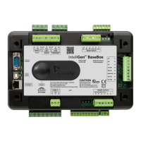
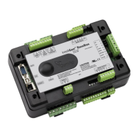
9.8.1. BaseBox controller ................................................................................................ 85
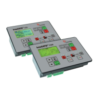
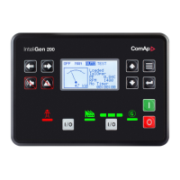
9.8.2. Controller with built-in display ................................................................................ 86
9.9. Binary Input wiring ...................................................................................................... 87
9.10. Binary Output wiring .................................................................................................. 87
9.10.1. Controllers without High-Side Low-Side Switch .................................................. 87
9.10.2. Controllers with High-Side Low-Side Switch ....................................................... 88
9.11. Examples of BI and BO Wiring ................................................................................... 90
9.11.1. Binary Outputs Wiring with I-RB16 ...................................................................... 90
9.11.2. Binary Inputs and Outputs Wiring ....................................................................... 90
9.12. Binary I/O on IS-BIN16/8 ........................................................................................... 91
9.12.1. Binary inputs on IS-BIN16/8 ................................................................................ 91
9.12.2. Binary outputs on IS-BIN16/8.............................................................................. 92
9.13. Binary output protections ........................................................................................... 92
9.14. Analog Input and Output wiring .................................................................................. 93
9.15. Analog Inputs on IS-AIN8 .......................................................................................... 94
10. Outputs refresh rates ................................................................................................. 97
11. External modules connection ..................................................................................... 98
11.1. Lost Communication Protection ................................................................................. 98
11.2. IS-BIN16/8 and IS-AIN8 ............................................................................................. 98
11.2.1. IS-AIN8, IS-BIN8/16 address setting ................................................................... 99
11.2.2. IS-AIN8, IS-BIN8/16 SW version check .............................................................. 99
11.2.3. Example of Wiring ............................................................................................... 99
11.3. IGS-PTM and IGL-RA15 .......................................................................................... 100
11.3.1. Example of Wiring ............................................................................................. 100
11.4. Connection of ECU on CAN1 with Other Modules Connected ................................. 101
11.4.1. I-CB wiring and configuration ............................................................................ 102
12. Communications ...................................................................................................... 103
12.1. Available Communication Ports ............................................................................... 103
12.2. Possible Connections per Port ................................................................................. 104
13. CAN Bus .................................................................................................................. 105
13.1. CAN bus Tx, Rx LED indication ............................................................................... 105
13.2. CAN and RS485 bus wiring ..................................................................................... 105
13.2.1. Wiring examples ............................................................................................... 106
14. Dongle installation ................................................................................................... 108
15. Sensors ................................................................................................................... 109
15.1. Sensor fail detection (FLS) ...................................................................................... 109
15.2. Default Sensors ....................................................................................................... 109
16. Regulation loops ...................................................................................................... 111

 Loading...


