ROBOT CONFIGURATION CUSTOMIZATION
25
Comau Robotics Product Instruction
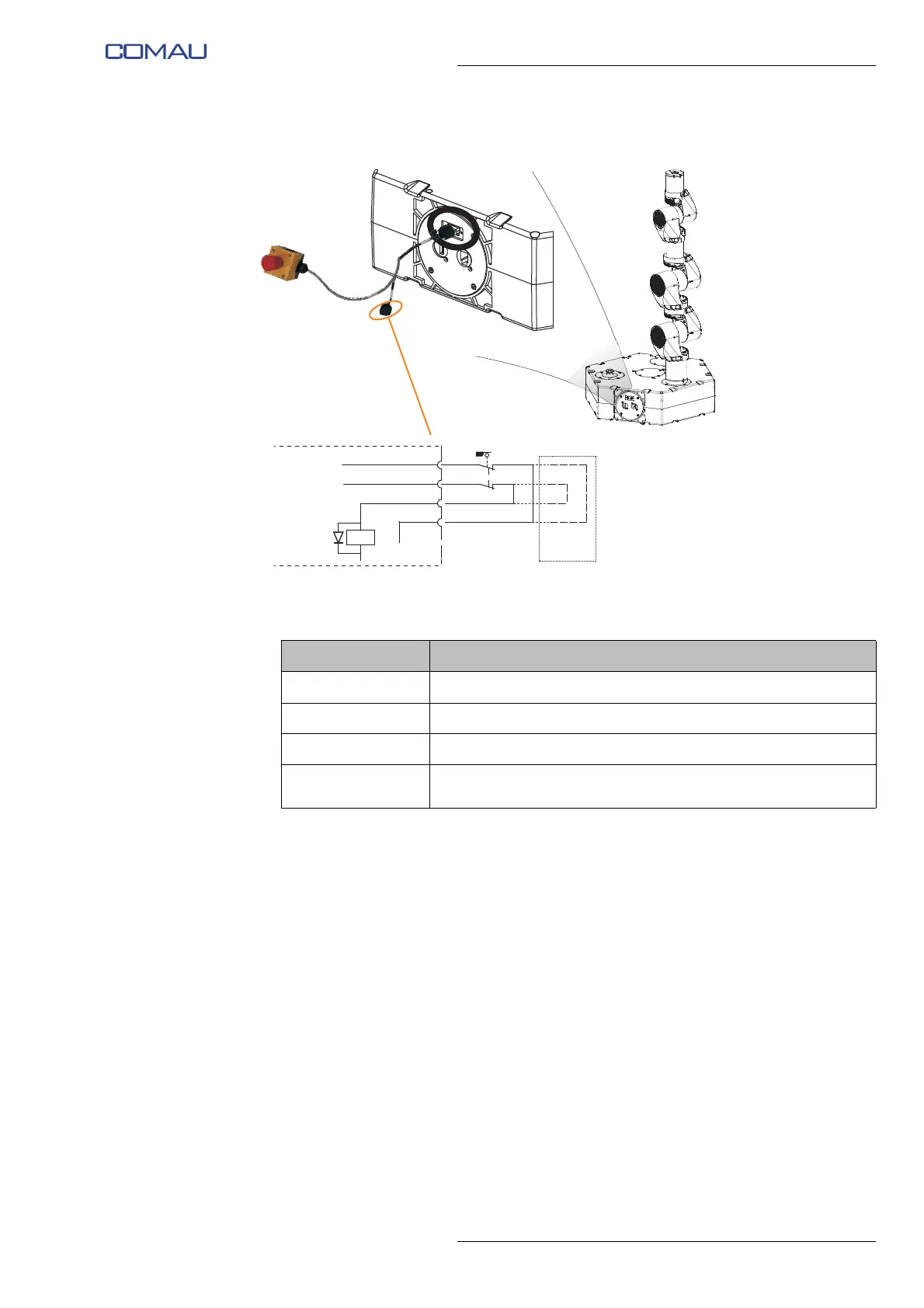
Fig. 3.5 - “Fence” input connection diagram - side e.DO
Tab. 3.2 - Connector pinout (pins relative to the input for guard
interlocking devices connection)
PIN Name / function
1 V_Out_Safe (24 Vdc)
2 0V (V_Out_Safe)
5 Fence CH1 (Connection to Relay K2, inside hexagonal base)
6
Fence CH2 (Connection to input on Raspberry, inside
hexagonal base)
Fence
Hexagonal base
(internal connections)
1
2
5
6
Mating
connector