Comau Robotics Product Instruction
26
ROBOT CONFIGURATION CUSTOMIZATION
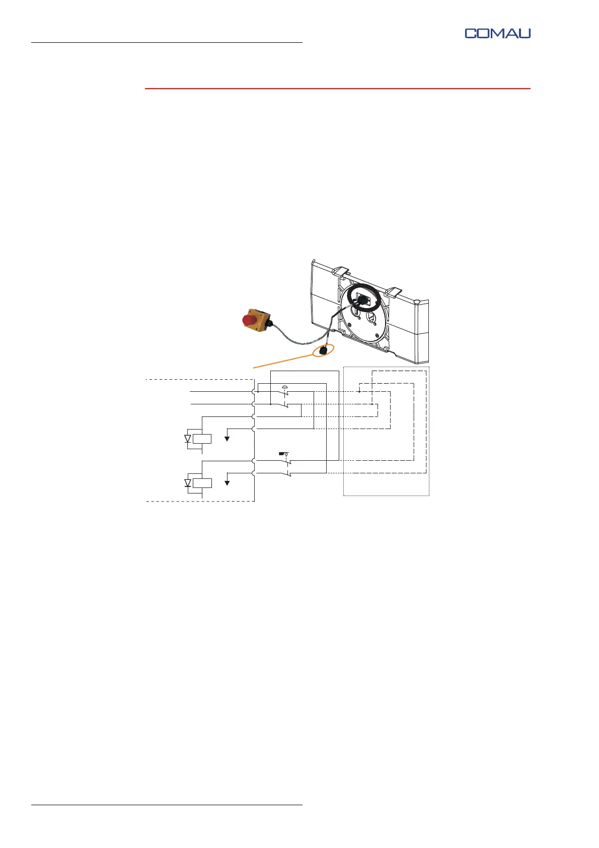
3.2.3 Simultaneous connection of additional emergency
push-button and interlocking device associated with
guards
The simultaneous connection of the additional emergency push-button and interlocking
device associated with guards can be carried out by wiring both devices on the 9-pole
D-Sub connector as shown in the previous
par. 3.2.1 and par. 3.2.2.
The connection diagram is shown below.
Fig. 3.6 - “E-Stop” input and “Fence” input simultaneous connection
diagram
Fence
5
6
E-stop
Hexagonal base
(internal connections)
1
2
3
4
Mating connector