ROBOT CONFIGURATION CUSTOMIZATION
33
Comau Robotics Product Instruction
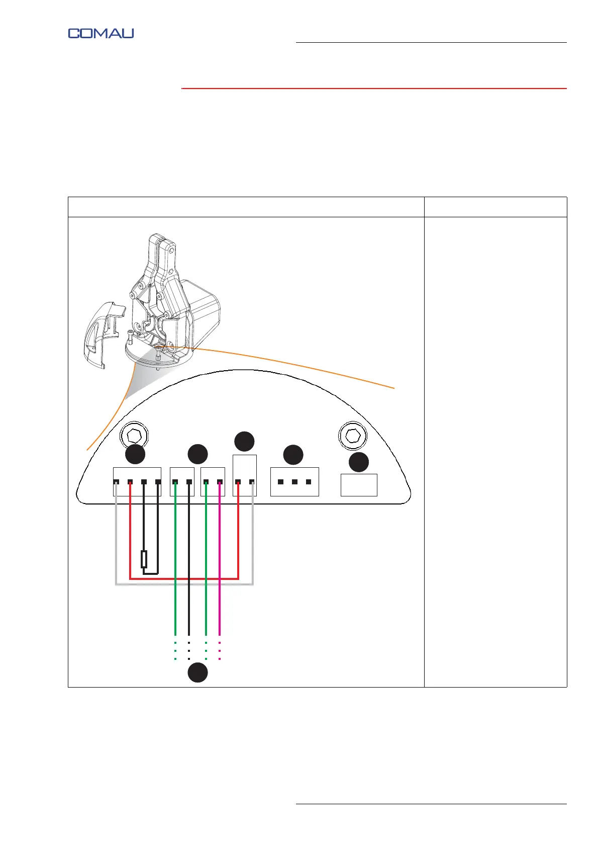
3.2.4.3 e.DO Gripper connection electrical circuit diagram
In the following diagram there are given the electrical connections necessary to be
performed on the e.DO Gripper electronic board (PCB), in order to allow its correct
operation.
Fig. 3.11 - Electrical diagram of e.DO Gripper connection
View Description
–A: “BUS OUT” connector
–B: “BUS IN” connectors
–C: “SUPPLY” connector
–D: “SERVO” connector
–E: Connector not used
– F: Connections coming
from the electronic board
(PCB) of the last Robot
joint
– R: Terminating resistor in
the CAN network