Comau Robotics Product Instruction
32
ROBOT CONFIGURATION CUSTOMIZATION
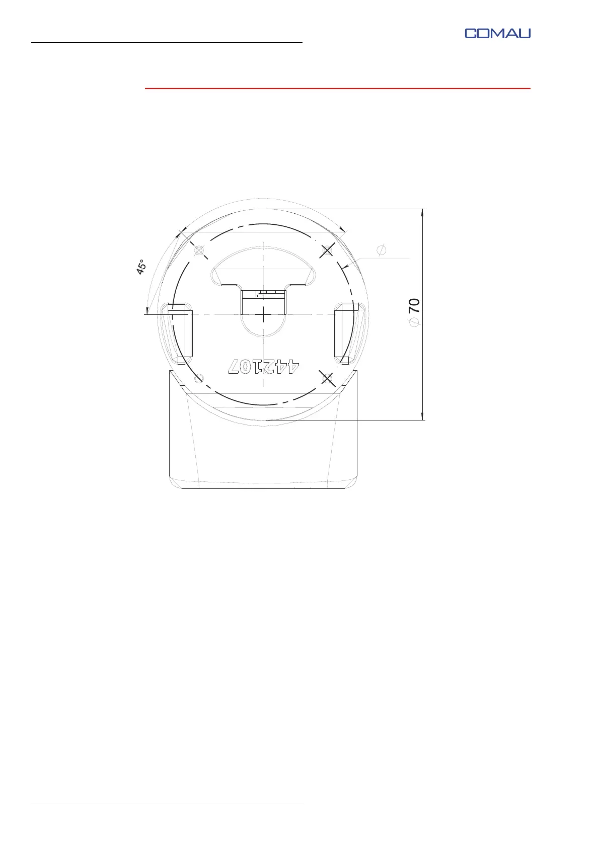
3.2.4.2.2 Flange hole diagram for e.DO Gripper fixing
The following drawing shows the diagram of holes present on the e.DO Gripper flange
to be used for the e.DO Gripper fixing to the e.DO Robot (dimensions in mm).
Fig. 3.10 - Flange hole diagram for e.DO Gripper