Comau Robotics Product Instruction
44
ROBOT CONFIGURATION CUSTOMIZATION
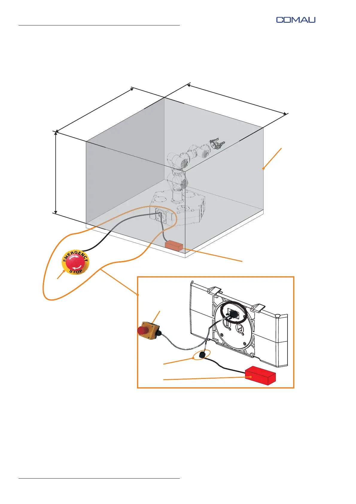
Fig. 3.12 - Example of perimeter protective guards installation
Minimum dimensions of perimeter protective guards; dimensions in mm
– A: Perimeter protective guards (to be carried out by the User)
– B: Safety limit switch to control the correct positioning of the guard (to be installed
by the User)
– C: Remote emergency push-button (present as standard with the Robot)
– D: Connector on which to connect the safety limit switch for positioning control of
the guard (“Fence” input).