Do you have a question about the Compaq Evo D500 and is the answer not in the manual?
Provides technical information about Compaq Evo, Deskpro EN, and Deskpro Workstation AP230 Personal Computers.
Lists manufacturers' documentation and online sources for more information on system components.
Explains the convention used for naming Compaq Deskpro units and their components.
Describes the location and methods to read the unit's serial number.
Outlines the notational guidelines used throughout the guide for clarity.
Lists and defines acronyms and abbreviations used in the document.
Provides an overview of Compaq Deskpro and Evo Personal Computers.
Describes the standard features and available options for the computer models.
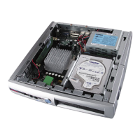
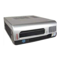
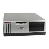
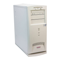
Details the physical aspects and form factors of the Compaq Deskpro models.
Explains the system architecture based on Intel processors and chipsets.
Lists environmental, electrical, and physical specifications for the computers.
Introduces the processor/cache memory subsystem of the computers.
Details the Celeron and Pentium III processors used in the systems.
Describes the system's memory configuration, including SDRAM DIMM sockets.
Details the configuration registers for the processor/memory subsystem.
Overviews the system architecture and topics covered in this chapter.
Describes the 32-bit Peripheral Component Interconnect (PCI) bus.
Explains the Accelerated Graphics Port (AGP) bus for high-performance graphics.
Details resource allocation, interrupts, and DMA requests.
Explains how system clock signals are generated and distributed.
Describes the RTC and CMOS functions provided by the 82801 ICH2 component.
Covers system functions like security, power management, and status.
Details system I/O map and functions of the ICH2 and I/O controller.
Introduces the chapter's topics on system board interfaces and I/O-mapped registers.
Describes the enhanced IDE interface with primary and secondary controllers.
Details the diskette drive interface and its operational phases.
Explains the two serial interfaces and their UART capabilities.
Describes the parallel interface and its three operational modes.
Covers the keyboard/pointing device interface and its operation.
Explains the USB interface, data formats, and programming.
Describes the audio subsystem, including legacy and AC'97 support.
Details the Network Interface Controller (NIC) features and support.
Introduces embedded graphics subsystems and available configurations.
Describes the graphics controller integrated into the 82815 GMCH component.
Details the NVIDIA TNT2 Pro AGP graphics controller.
Explains monitor power control using VESA DPMS protocol.
Describes the DB-15 connector for analog monitor connection.
Describes the power supply and method of general power and signal distribution.
Details the power supply assembly and its programmable logic control.
Explains the distribution of voltages to system components.
Illustrates general signal distribution between system subassemblies.
Defines the Basic Input/Output System (BIOS) and its functions.
Describes the process of updating system BIOS firmware.
Covers functions related to the boot process and Power-On Self-Test (POST).
Details the system configuration options available through the Setup utility.
Lists BIOS functions supporting intelligent manageability applications.
Explains the Plug ’n Play (PnP) support features.
Describes power management support including Independent PM, APM, and ACPI.
Details BIOS support for USB keyboards during setup.
Lists error codes and probable causes for system errors.
Provides codes for system memory and video/graphics failures.
Lists POST error messages and their probable causes.
Lists system error messages from 1xx-xx range.
Lists memory error messages from 2xx-xx range.
Lists keyboard error messages from 30x-xx range.
Lists printer error messages from 4xx-xx range.
Lists video error messages from 5xx-xx range.
Lists diskette drive error messages from 6xx-xx range.
Lists serial interface error messages from 11xx-xx range.
Lists modem error messages from 12xx-xx range.
Lists hard drive error messages from 17xx-xx range.
Lists video error messages from 24xx-xx range.
Lists SCSI interface error messages.
Lists pointing device error messages.
Introduces the ASCII code set including decimal and hexadecimal values.
Describes the standard Compaq keyboard and its types.
Explains how keystrokes are processed and scan codes are generated.
Details the PS/2 and USB keyboard interface connectors and pinouts.
Introduces the Compaq/NVIDIA TNT2 Pro AGP Graphics Card.
Describes the high-performance 2D and 3D display imaging capabilities.
Lists the graphics display modes supported by the NVIDIA TNT2 Pro.
Lists compatible operating systems and programming environments.
Details monitor power control and card power consumption.
Describes the display/monitor and feature connectors.
Introduces the Compaq/NVIDIA Quadro2 EX and MXR AGP Graphics Cards.
Describes the high-performance 2D and 3D display imaging capabilities.
Lists the 2D graphics display modes supported by the NVIDIA Quadro2 MXR.
Lists compatible operating systems and programming environments.
Details monitor power control and card power consumption.
Describes the display/monitor and feature connectors.
Introduces the Compaq/Matrox Millennium G450 AGP Graphics Card.
Describes the high-performance 2D and 3D display imaging capabilities.
Lists the graphics display modes supported by the Matrox Millennium G450.
Lists compatible operating systems and programming environments.
Details monitor power control and card power consumption.
Describes the display/monitor and feature connectors.
Introduces the Compaq/Adaptec 29160N SCSI Host Adapter.
Describes the adapter's architecture and high-performance SCSI interfacing.
Details SCSI adapter configuration and control.
Lists the operating specifications for the Ultra SCSI Host Adapter.
Describes the internal and external SCSI connectors.