Technical Reference Guide
7.2 POWER DISTRIBUTION
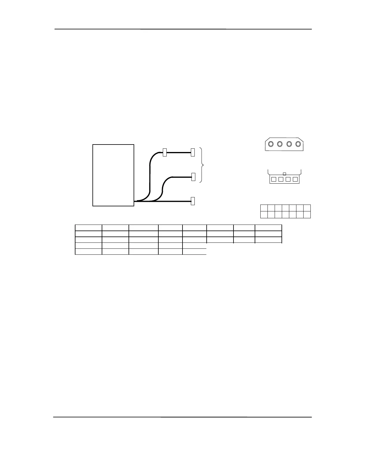
7.2.1 3.3/5/12 VDC DISTRIBUTION
The power supply assembly includes a multi-connector cable assembly that routes +3.3 VDC, +5
VDC, -5 VDC, +12 VC, and -12 VDC to the system board as well as to the individual drive
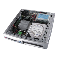
assemblies. Figure 7-2 shows the power supply cabling for the Deskpro EN SFF series.
P3, 4
System
Board
P2
P1
P3
P4
Drive
Assemblies
Power Supply
Assembly
(p/n 165997)
6
13
7
14
3
10
2
9
11
4
12
5
1
8
P1
4 3 2 1
P2
1 2 3 4
Conn. # Pin 1 Pin 2 Pin 3 Pin 4 Pin 5 Pin 6 Pin 7
P1 +3.3 +3.3 AUX RTN +5 RTN +5 RTN
P1 [1] +3.3 -12 FO PS On +5 AUX FS +12 VDC
P2 +5 GND GND +12
P3 +12 GND GND +5
NOTES:
[1] This row represents pins 8-14 of connector P1.
All + and - values are VDC
.
RTN = Return (signal ground)
GND = Power ground
RS = Remote sense
FO = Fan off
FS = Fan speed
Figure 7–2. Small Form Factor Power Cable Diagram
Compaq Deskpro and Evo Personal Computers
Featuring Intel Celeron and Pentium III Processors
Fifth Edition - March 2002
7-5