Chapter 2 System Overview
2.3.3 BOARD LAYOUTS
27
25
35
1
4
2
31
23
24
5
24
23
26
29
22
30
21
28
19
16
15
17
13
7
6
20
9
18
10
14
12
11
8
32
2
3
34
33
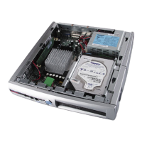
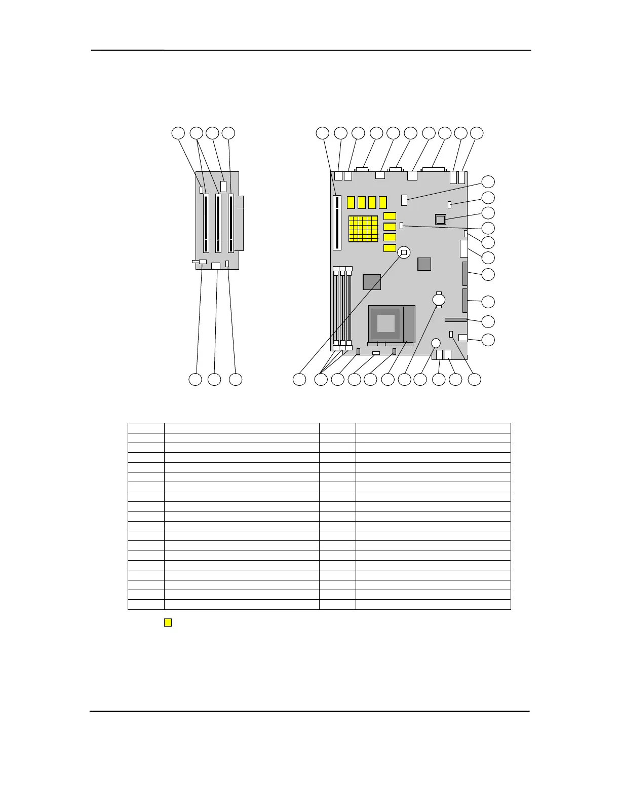
System Board PCA# 010633, 010700, 011035, 011308 or 011311
Riser Board PCA# 010636
Item
Description
Item Description
1 SCSI hard drive LED connector 19 Power supply connector
2 PCI bus expansion connectors 20 Secondary IDE connector
3 AOL/SOS connector 21 Primary IDE connector
4 Riser card connector 22 Diskette drive connector
5 PS/2 mouse connector 23 CD-ROM audio connector (right angle)
6 PS/2 keyboard connector 24 CD-ROM audio connector (vertical)
7 Monitor connector 25 Headphone output jack [3]
8 Top: USB port B; Bottom: USB port A 26 Microphone input jack [3]
9 Serial port COM2 connector 27 PCB speaker [4]
10 Network interface connector 28 CMOS battery
11 Parallel port LPT1 connector 29 Processor socket
12 Audio line in jack [3] 30 Hard drive activity LED
13 Audio line out jack [3] 31 Power button
14 Serial port COM1 header [1] 32 Power LED
15 Smart Cover Lock solenoid connector 33 DIMM sockets
16 Firmware Hub (BIOS ROM) 34 CMOS memory clear button
17 Password jumper [2] 35 Smart Cover Sensor switch
18 Speaker connector [3] -- --
NOTES:
NVIDIA graphics components installed on PCA# 010633 and 011308 only.
[1] Header connects to COM1 DB-9 connector on I/O panel via cable assembly.
[2] Jumper installed, password enabled. Jumper removed, password is cleared.
[3] Not installed on PCA# 011035.
[4] Installed on PCA# 011035 only.
Figure 2–7. Small Form Factor Board Layouts
Compaq Deskpro and Evo Personal Computers
Featuring Intel Celeron and Pentium III Processors
Fifth Edition – March 2002
2-10