Technical Reference Guide
7.2.2 LOW VOLTAGE DISTRIBUTION
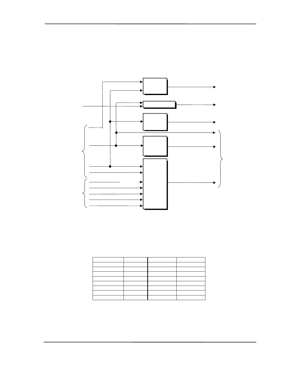
Voltages less than 3.3 VDCincluding processor core (VccP) voltage are produced through
regulator circuitry on the system board.
NOTE:
VccP (see text)
Regulator
Circuit
+12 VDC
VID0
Processor
VID1
VID2
VID3
VTT (+1.5) VDC)
Regulator
Circuit
Power Supply
+5 VDC
+3.3 VDC
+5 AUX
DIMMs
S3 Mode
RAM PWR
Circuit
3.3 VDC
+5 VDC
LM317
Regulator
Circuit
+2.5 VDC
Pull-Up Logic
Processor
+3.3 VDC
VID25MV
AGP Bus
VDDQ [1]
+5 VDC
AGP Bus
Type Det-
AGP PWR
[1] VDDQ = 1.5 for AGP 4X cards (Type Det- grounded), 3.3 for AGP 1X/2X cards
(Type Det- left open).
Figure 7–4. Low Voltage Supply and Distribution Diagram
The VccP regulator produces the VccP (processor core) voltage according to the strapping of
signals VID3..0 by the processor. The possible voltages available are listed as follows:
VID 3..0 VccP VID 3..0 VccP
0000 2.05 VDC 1000 1.65 VDC
0001 2.00 VDC 1001 1.60 VDC
0010 1.95 VDC 1010 1.55 VDC
0011 1.90 VDC 1011 1.50 VDC
0100 1.85 VDC 1100 1.45 VDC
0101 1.80 VDC 1101 1.40 VDC
0110 1.75 VDC 1110 1.35 VDC
0111 1.70 VDC 1111 1.30 VDC
Refer to Chapter 3 for a listing of the core voltages set by the Celeron (Table 3-1) and Pentium III
(Table 3-2) processors.
Compaq Deskpro and Evo Personal Computers
Featuring Intel Celeron and Pentium III Processors
Fifth Edition - March 2002
7-7