Technical Reference Guide
2.3.2 CHASSIS LAYOUTS
This section describes the internal layouts of the chassis. For detailed information on servicing
the chassis refer to the multimedia training CD-ROM and/or the maintenance and service guide
for these systems.
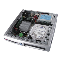
The chassis layout for the Small Form Factor is shown in Figure 2-4. Service features include:
♦ Easily-removable card cage assembly.
♦ Tilting drive bay assembly (for easy access to processor and memory sockets).
Smart Cover Lock
Solenoid
Card Cage
Assembl
Slot 2
Slot 3
Slot 1
Slots On Backplane,
Rear View
PCI Conn. 2
PCI Conn. 3
PCI Conn. 1
System Board
Upper Drive Bays
(Tilting Assembly)
Power Supply
Back
Speaker Assembly [1]
Lower Drive Bay
Front
NOTE:
[1] Installed on systems with integrated AC97 audio.
Figure 2–4. Small Form Factor Chassis Layout, Top View
Compaq Deskpro and Evo Personal Computers
Featuring Intel Celeron and Pentium III Processors
Fifth Edition - March 2002
2-7