Chapter 7 Power and Signal Distribution
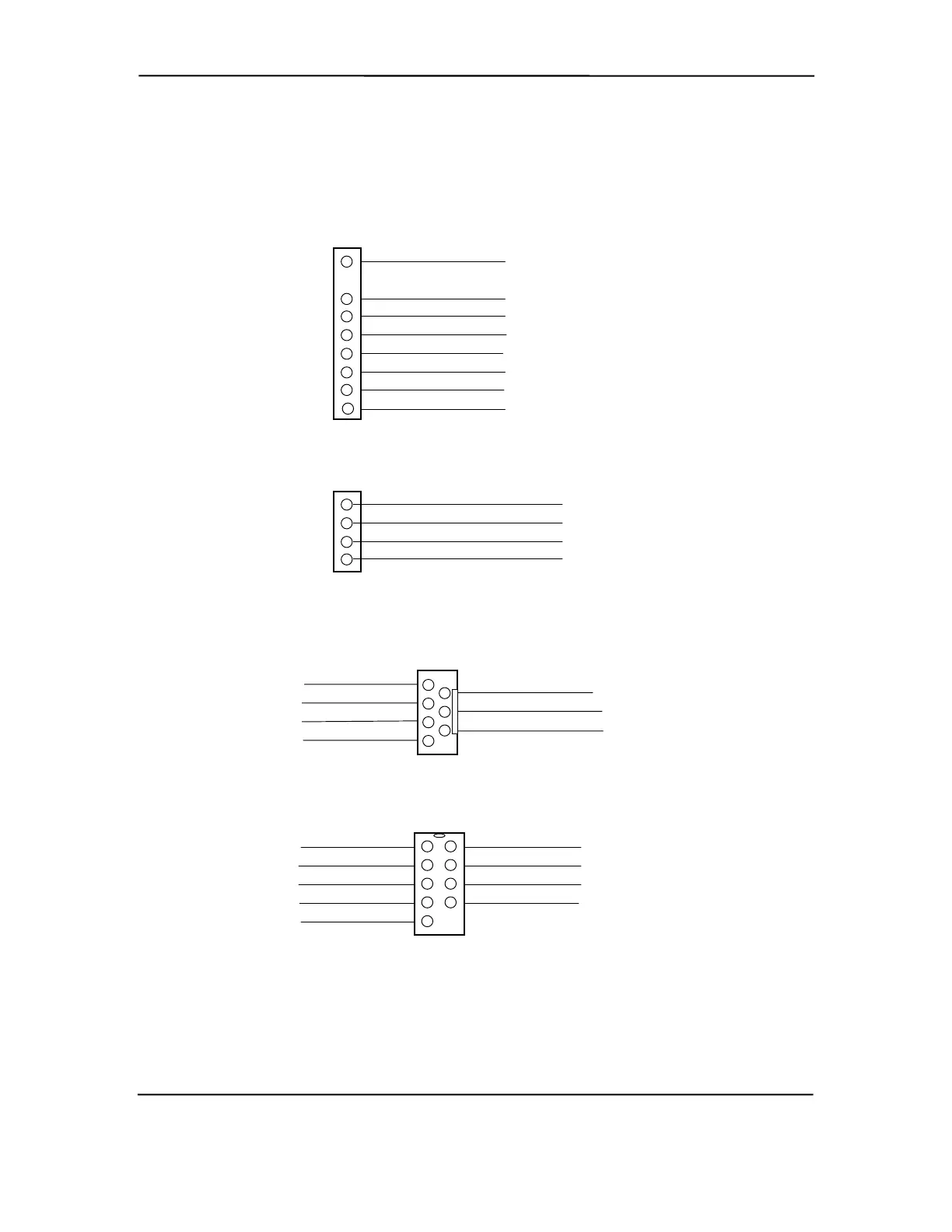
Power Button/LED Header P5
(Slim Desktop/Configurable Minitower only)
1 HD LED anode
3 HD LED cathode
4 PWR LED anode
9 SCSI HD LED [1]
8 SCSI HD LED [1]
7 PWR button (+)
6 PWR button (gnd)
5 PWR LED cathode
CD Audio Header P7
1 Ground
3 Ground
4 Audio (right channel)
2 Audio (left channel)
AOL/SOS Header P12
BIOS Fail 1
Fan Alert 5
Ground 7
Intrusion 3
2 OS Fail
6 Pwr
4 Thermal
Serial Port A/COM1 Header P16
(Small Form Factor only)
Carrier Detect
TX Data 3
Data Terminal Ready 4
Ground 5
RX Data 2
6 Data Set Ready
8 Clear to Send
9 Ring Indicate
7 Request to Send
NOTE:
No polarity consideration required for connection to speaker header P6 or SCSI HD LED header P29.
[1] Separate cable connection for these two pins (equivalent of header P29 on other systems).
Figure 7–7. Header Pinouts
Compaq Deskpro and Evo Personal Computers
Featuring Intel Celeron and Pentium III Processors
Fifth Edition - March 2002
7-10