Technical Reference Guide
5.4.2 COM1 PORT HEADER
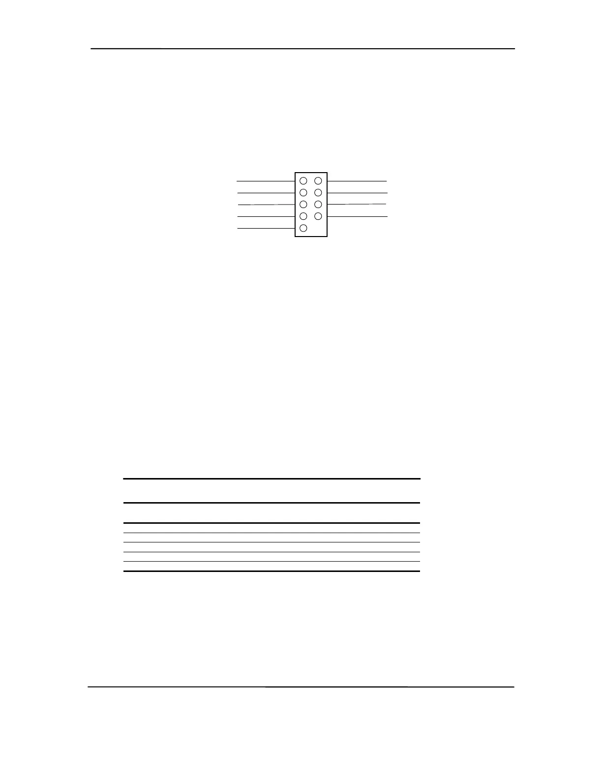
The Small Form Factor system board includes a header that connects to the COM1 port’s DB-9
connector on the rear chassis I/O panel through a cable assembly. The header pinout is shown in
the following figure:
TX Data 3
CD 1
DTR 4
Gnd 5
RX Data 2
6 DSR
8 CTS
9 RI
7 RTS
Figure 5-4. COM1 Serial Interface Header (Small Form Factor system board only)
5.4.3 SERIAL INTERFACE PROGRAMMING
Programming the serial interfaces consists of configuration, which occurs during POST, and
control, which occurs during runtime.
5.4.3.1 Serial Interface Configuration
The serial interface must be configured for a specific address range (COM1, COM2, etc.) and also
must be activated before it can be used. Address selection and activation of the serial interface are
affected through the PnP configuration registers of the LPC47B357 I/O controller.
The serial interface configuration registers are listed in the following table:
Table 5–8. Serial Interface Configuration Registers
Table 5-8.
Serial Interface Configuration Registers
Index
Address
Function
R/W
30h Activate R/W
60h Base Address MSB R/W
61h Base Address LSB R/W
70h Interrupt Select R/W
F0h Mode Register R/W
NOTE:
Refer to LPC47B357 data sheet for detailed register information.
Compaq Deskpro and Evo Personal Computers
Featuring Intel Celeron and Pentium III Processors
Fifth Edition - March 2002
5-9