Chapter 7 Power and Signal Distribution
7.3 SIGNAL DISTRIBUTION
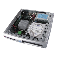
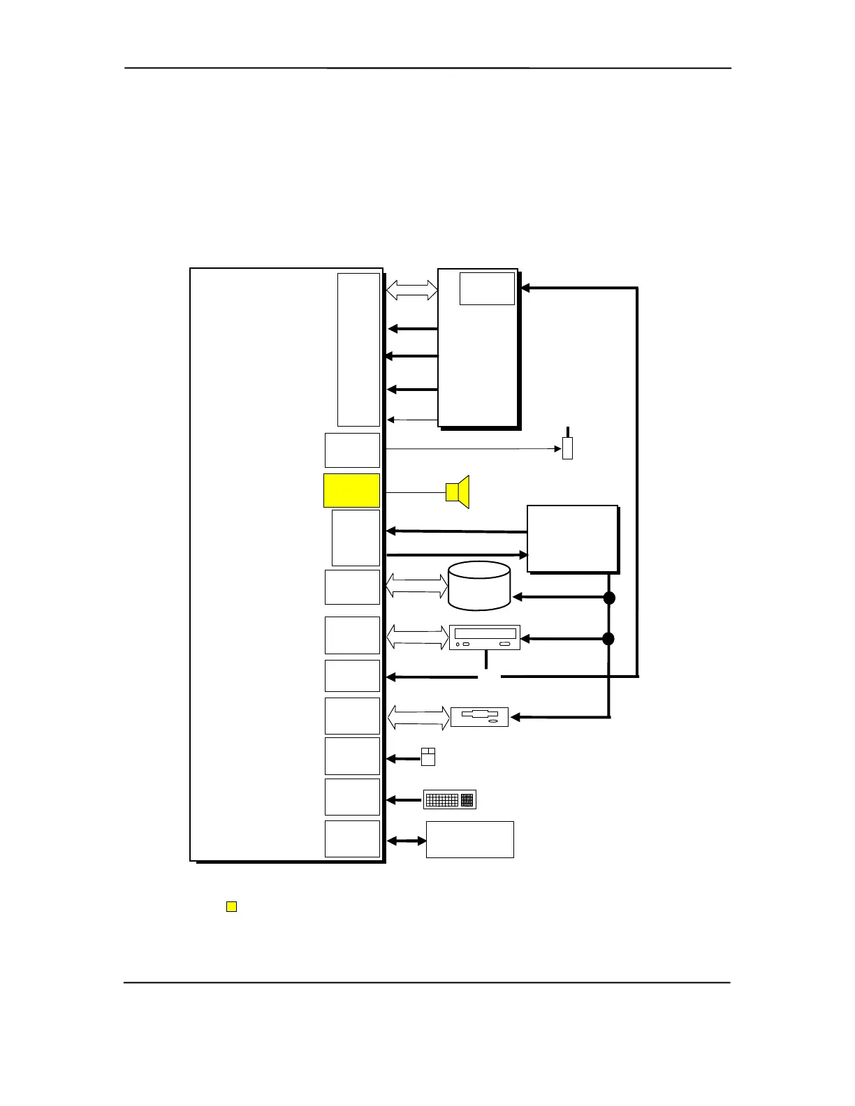
Figures 7-4 and 7-5 show general signal distribution between the main subassemblies of the
system units.
NOTES:
[1] Connector mounted on rear chassis panel.
PCA #010633 and 010700 only. PCA #011035 has speaker mounted on system board.
L/R Audio
or
Solenoid
Smart Cover Lock/Unlock
Conn.
P200
Fan Cntrl., PS On
L/R Audio
CD Audio
Conn P7
Spkr.
Conn. P6
Audio
COM1 (Serial A)
DB-9 Conn. [1]
COM1
Conn P89
Cover
Sense
SCSI
LED
CD Audio
Power
Supply
Assembly
Kybd
Conn J66
Mouse
Conn J67
5
12 VDC
5, 12 VDC
Diskette Drive
Dsk I/F
Dsk.
Conn P10
Mouse
Keyboard
CD-ROM
IDE I/F
Sec. IDE
Conn P21
Pri. IDE
Conn P20
Power
Conn P1
Riser
Card
Conn
J50
5, 12 VDC
IDE
Hard Drive
IDE I/F
3/5/12 VDC, 3/5 AUX
PCI
Bus
Riser Card
(PCA #
010636)
CD Audio
Conn P7
AOL/SOS
System
Board
(PCA # 010633,
010700, 011035,
011308, or 011311)
Figure 7–5. Small Form Factor Signal Distribution Diagram
Compaq Deskpro and Evo Personal Computers
Featuring Intel Celeron and Pentium III Processors
Fifth Edition - March 2002
7-8