Chapter 7 Power and Signal Distribution
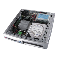
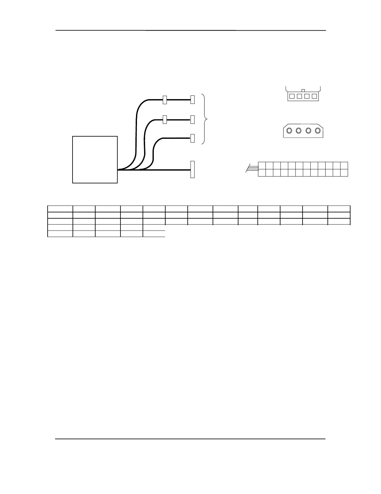
Figure 7-3 shows the power supply cabling for Deskpro EN SDT/CMT series units.
P7
P1
P5
P2
P4
P6
To
System
Board
P7
P1
To
Drive
Assemblies
Power Supply
Assembly
(SP# 161071
or 386461)
4 3 2 1
P2-P6
1 2 3 4
9
21
8
20
10
22
6
18
7
19
3
15
4
16
5
17
2
14
11
23
12
24
1
13
Conn. # Pin 1 Pin 2 Pin 3 Pin 4 Pin 5 Pin 6 Pin 7 Pin 8 Pin 9 Pin 10 Pin 11 Pin 12
P1 +3.3 +3.3RS RTN +5 RTN +5 AuxRtn FO +5 Aux +12 +3.3Aux FSpd
P1 [1] +3.3 -12 Rtn PS On RTN RSRTN RTN -5 +5 +5 +3.3RS FS
P2 +5 GND GND +12
P3 +12 GND GND +5
NOTES:
[1] This row represents pins 13-24 of connector P1.
All + and - values are VDC
.
RTN = Return (signal ground)
GND = Power ground
RS = Remote sense
FO = Fan off
FSpd = Fan speed
FS = Fan Sink
Figure 7–3. Slim Desktop/Configurable Minitower Power Cable Diagram
Compaq Deskpro and Evo Personal Computers
Featuring Intel Celeron and Pentium III Processors
Fifth Edition - March 2002
7-6