Technical Reference Guide
4.3.2 AGP CONFIGURATION
AGP bus operations require the configuration of certain parameters involving system memory
access by the AGP graphics adapter. The AGP bus interface is configured as a PCI device
integrated within the north bridge (GMCH, device 1) component. The AGP function is, from the
PCI bus perspective, treated essentially as a PCI/PCI bridge and configured through PCI
configuration registers (Table 4-6). Configuration is accomplished by BIOS during POST.
NOTE: Configuration of the AGP bus interface involves functions 0 and 1 of the
GMCH. Function 0 registers (listed in Table 3-4) include functions that affect basic
control (GART) of the AGP.
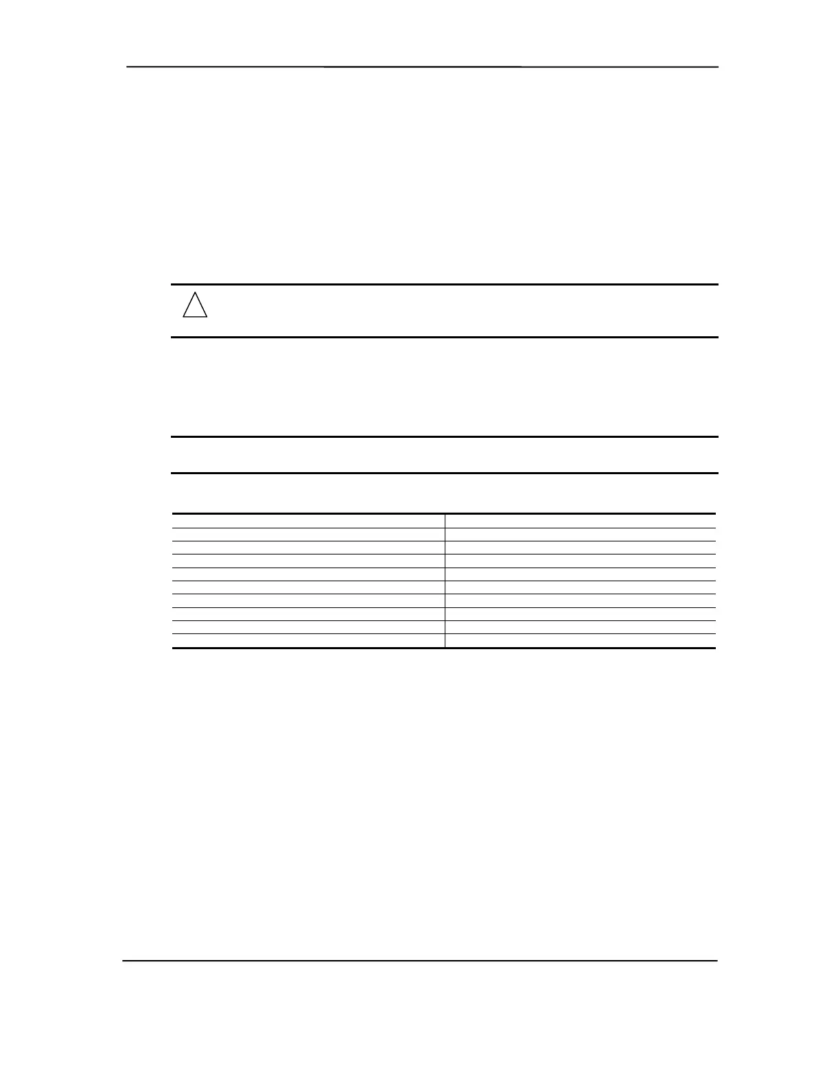
Table 4-6. PCI/AGP Bridge Configuration Registers (MCH, Function 1)
Table 4-6.
PCI/AGP Bridge Function Configuration Registers (GMCH, Function 1)
PCI
Config.
Addr.
Register
Reset
Value
PCI
Config.
Addr.
Register
Reset
Value
00, 01h Vendor ID 8086h 1Bh Sec. Master Latency Timer 00h
02, 03h Device ID 1131h 1Ch I/O Base Address F0h
04, 05h Command 0000h 1Dh I/O Limit Address 00h
06, 07h Status 0020h 1E, 1Fh Sec. PCI/PCI Status 02A0h
08h Revision ID 00h 20, 21h Memory Base Address FFF0h
0A, 0Bh Class Code 0406h 22, 23h Memory Limit Address 0000h
0Eh Header Type 01h 24, 25h Prefetch Mem. Base Addr. FFF0h
18h Primary Bus Number 00h 26, 27h Prefetch Mem. Limit Addr. 0000h
19h Secondary Bus Number 00h 3Eh PCI/PCI Bridge Control 00h
1Ah Subordinate Bus Number 00h 3F-FFh Reserved 00h
NOTE:
Assume unmarked locations/gaps as reserved. Refer to Intel documentation for detailed
register descriptions.
The AGP graphics adapter (actually its resident controller) is configured as a standard PCI device.
Compaq Deskpro and Evo Personal Computers
Featuring Intel Celeron and Pentium III Processors
Fifth Edition - March 2002
4-13