41Mounting and installation work
SWITCH
J1 CPU
BOARD
REL4
MAIN CONTACT
PWR
MAIN SUPPLY
X9
CONT.SIGN
SAFETY
PE
L
N PE
F2
1AT
F3
1AT
F1
200mAF
CYLINDER LEVEL SENSOR
X7
X1 X6
DRAIN
L N L N
INLET
J7L
J6N
J4N
L1
N
J
F5
Q5
S1
230V1~ 50..60Hz
CTRL V+
12 123
GND
BASIC
0-10V
On/Off
24V
5V
PRO
JP4
JP3
JP2
JP1
SC1SC2
X8
F4 1AT
N L SW N SWL
V+GND CTRL
SC1SC2
– +
0-10V
A1
V+GND CTRL
On/Off
A2
K
B1
red yellow green
Cylinder
Drain Factor
Power Limit
Manual Drain
Low Conduct.
Standby Drain
Force Drain
Cylinder A/D
GFCI-Mode
Offset
Settings
0
DriverRFI
ON
1 2 3 4 5 6
J8
J1
S1
S2
S3
S4
max.
T /
Control board Driver board
Smart Card
Cylinder RD 422
Inlet valve
Drain valve
Set JP2 and JP3
Remove JP1
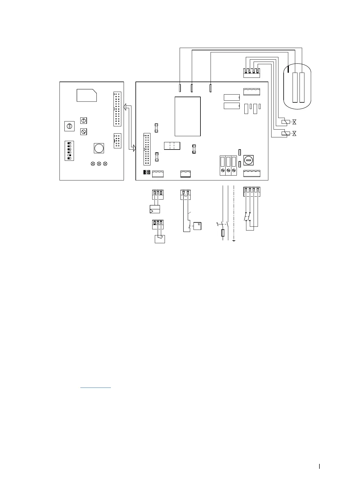
5.6.2 Wiring diagram Condair Sigma 4 kg/h
A1 Continuous controller (active 0-10V) or control sig-
nal input from Condair Delta SPA Control Box
A2 On/Off controller (passive 24VDC), set jumper on
JP1
B1 Safety humidistat / Safety thermostat
F1 Internal fuse power board: control signal
(200 mA, fast acting)
F2 Internal fuse power board: control 5 V
(1 A, slow acting)
F3 Internal fuse power board: control 24 V
(1 A, slow acting)
F4 Internal fuse power board: control voltage
(1 A, slow acting)
F5
External fuse supply voltage (fuse values see table
in chapter 5.6.4.8)
J Short circuited, if no external monitoring devices are
connected
JP1 Set jumper for voltage output on X1, V+ = 5 V (remove
jumper JP1)
JP2 Set jumper for voltage output on X1, V+ = 24 V (remove
jumper JP2)
JP3 Jumper must be removed
JP4 Jumoper must be set
K External safety chain (24 VDC)
Q5 External service switch voltage supply
S1 Unit switch
REL4 Relay heating
S1 Rotary switch "Cylinder type"
S2 Potentiometer "Drain factor"
S3 Potentiometer "Power limitation"
S4 DIP switch "General unit settings"
X1 Connection terminal control signal
X6 Connection terminal safety chain
X7 Connection terminal inlet and outlet valve
X8 Connection terminal unit switch
X9 Connection terminal voltage supply
Abb. 15: Wiring diagram Condair Sigma 4 kg/h