49Mounting and installation work
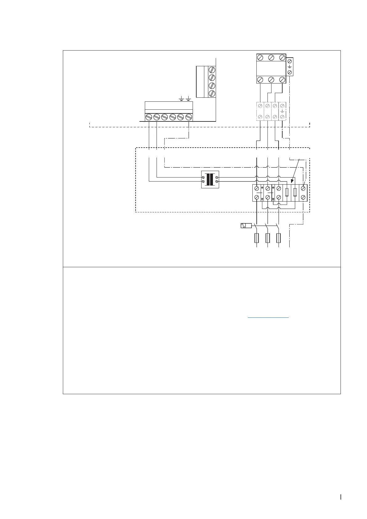
5.6.4.6 Connecting the voltage supply to the Condair Sigma 5-65 kg/h via Option TR
K1
THV
L1 L2 L3
X3
MAIN SUPPLY
L1 N SC1SC2
X5
1 2 3 4
SWITCH
400 V/3~/50..60 Hz
F2
Q2
L2 L3 PEL1
N PE
L1
L1
L2
L3
PE
Control
compartment
Option TR (3Ph)
6.3 A,
slow acting
The voltage supply (L1, L2, L3 and PE) is to be connected in accordance with the wiring diagram to
the corresponding terminals of option "TR". The connecting cable must be led through a cable gland
into the control compartment.
The installation of the fuses "F2" and the electrical isolator "Q2" (all pole disconnecting device with
a minimum contact clearance of 3 mm, supplied by others) in the mains supply line are mandatory.
Note: The table with the fuse values for fuses "F3" can be found in chapter 5.6.4.5.
For safety reasons the additional installation of a residual current circuit breaker in the mains supply
line (supplied by others) is recommended. However, the local electrical installation regulations must
be observed and adhered to..
The electrical isolator must be mounted in direct proximity of the control compartment (max. distance
1 m) and must be easily accessible in a height between 0.6 m and 1.9 m (recommended: 1.7 m).
CAUTION! Make sure the voltage indicated on the type plate meets the local mains voltage. Other-
wise, do not connect the unit.
The cross-section of the mains cable must comply with the applicable local regulations.