Menu 10
Parameter
structure
Keypad and
display
Parameter x.00
Parameter description
format
Advanced parameter
descriptions
Serial comms
protocol
Performance
144 Mentor MP Advanced User Guide
www.controltechniques.com Issue Number: 4
This parameter gives the phase rotation of the L1, L2 and L3 terminals, with relation to E1 and E3 when voltage is first detected on L1, L2 and L3.
A supply loss trip will result if a phase is missing.
Example
L123 E21 phase rotation on L1, L2, L3 is clockwise, terminal E1 is connected to the same phase as L2 terminal, terminal E3 is connected to the same
phase as L1 terminal.
The input frequency measured on the auxiliary terminals.
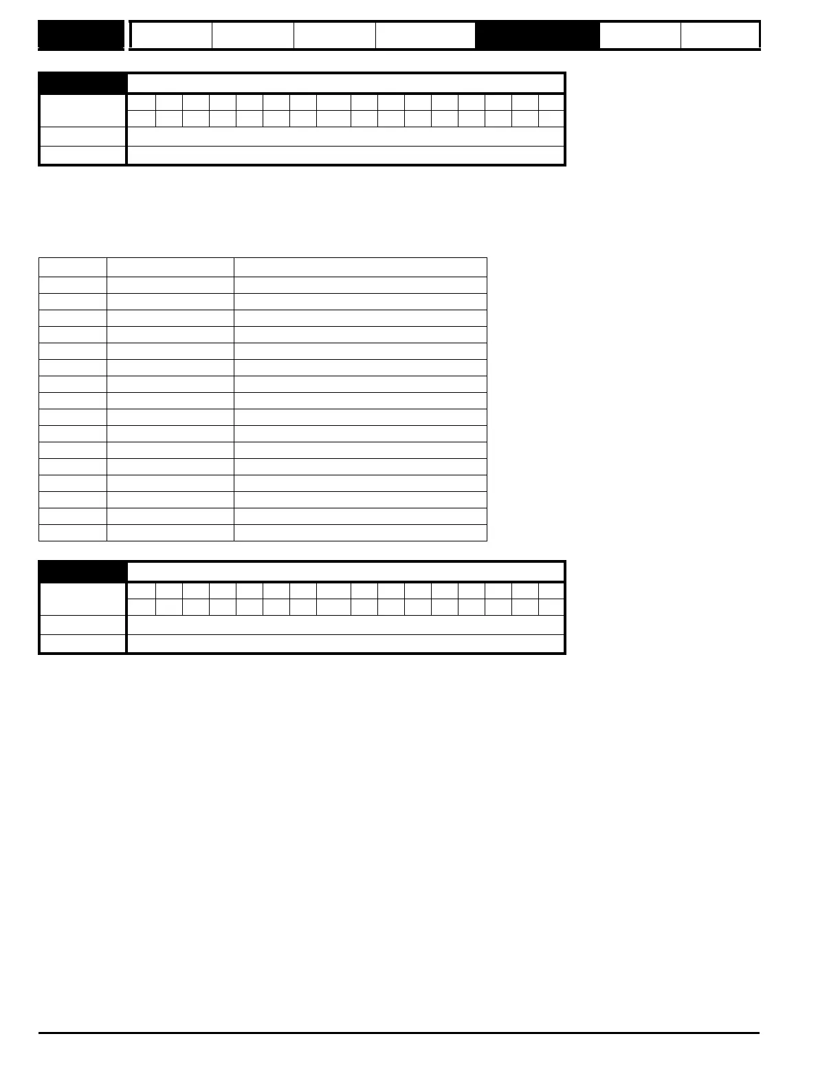
10.76 Phase rotation
Coding
Bit SP FI DE Txt VM DP ND RA NC NV PT US RW BU PS
111
Range 0 to 15 (see table below)
Update rate Background read
Pr 10.76 Text Comment
0 No L123 No voltage detected on L1, L2, L3
1 L123 E13 L1, L2, L3 clockwise
2 L123 E12 L1, L2, L3 clockwise
3 L123 E32 L1, L2, L3 clockwise
4 L123 E31 L1, L2, L3 clockwise
5 L123 E21 L1, L2, L3 clockwise
6 L123 E23 L1, L2, L3 clockwise
7 L321 E13 L1, L2, L3 anticlockwise
8 L321 E23 L1, L2, L3 anticlockwise
9 L321 E21 L1, L2, L3 anticlockwise
10 L321 E31 L1, L2, L3 anticlockwise
11 L321 E32 L1, L2, L3 anticlockwise
12 L321 E12 L1, L2, L3 anticlockwise
13 L120 L3 missing
14 L103 L2 missing
15 L023 L1 missing
10.77 Input frequency
Coding
Bit SP FI DE Txt VM DP ND RA NC NV PT US RW BU PS
2111
Range 0 to 100.00
Update rate Background read