Parameter structure Keypad and display Parameter x.00
Parameter description
format
Advanced parameter
descriptions
Serial comms
protocol
Performance
6 Mentor MP Advanced User Guide
www.controltechniques.com Issue Number: 4
Coding
The coding defines the attributes of the parameter as follows.
Defines the sub block headers. Can be used by the MP-Keypad to
display the same strings as the SM-Keypad.
The OR of Pr 23.03 to Pr 23.09. To be used by the MP-Keypad.
When this parameter is set to 1 the associated pre-defined sub block is
accessible. When this parameter is 0 the associated pre-defined block is
bypassed.
1.2 Pre-defined sub blocks
setup
Coding Attribute
{X.XX} Copied Menu 0 or advanced parameter
Bit 1 bit parameter: ‘On’ or ‘OFF’ on the display
Bi Bipolar parameter
Uni Unipolar parameter
Txt Text: the parameter uses text strings instead of numbers.
SP Spare: not used
FI
Filtered: some parameters which can have rapidly changing
values are filtered when displayed on the drive keypad for
easy viewing.
DE
Destination pointer parameter: This parameter can be used
to set up the location (i.e. menu/parameter number) where
the destination data is to be routed.
VM
Variable maximum: the maximum of this parameter can
vary.
DP
Decimal place: indicates the number of decimal places used
by this parameter.
ND
No default: when defaults are loaded (except when the drive
is manufactured or on EEPROM failure) this parameter is
not modified.
RA
Rating dependant: this parameter is likely to have different
values and ranges with drives of different voltage and
current ratings. Parameters with this attribute will not be
transferred to the destination drive by a SMARTCARD when
the rating of the destination drive is different from the source
drive if the drive voltage ratings are different or the file is a
parameter file. However, the value will be transferred if only
the current rating is different and the file is a differences
from default type file.
NC
Not copied: not transferred to or from SMARTCARD during
copying.
NV Not visible: not visible on the keypad.
PT Protected: cannot be used as a destination.
US
User save: saved in drive EEPROM when the user initiates
a parameter save.
RW Read/write: can be written by the user.
RO Read only: can only be read by the user
BU
Bit default one/unsigned: Bit parameters with this flag set to
one have a default of one (all other bit parameters have a
default of zero. Non-bit parameters are unipolar if this flag is
one.
PS
Power-down save: parameter automatically saved in drive
EEPROM when the under volts (UV) trip occurs. Power-
down save parameters are also saved in the drive when the
user initiates a parameter save.
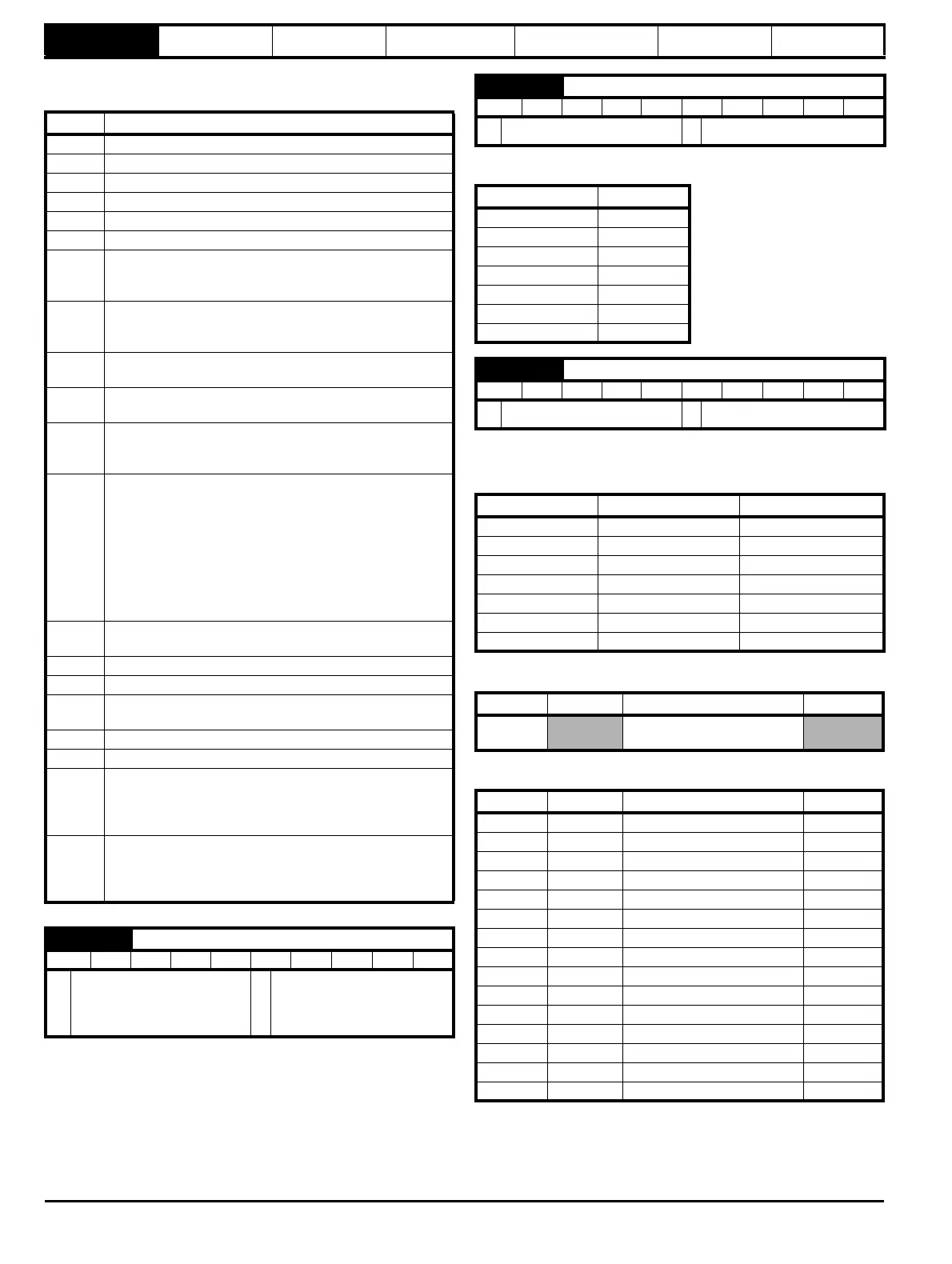
23.01 Sub block headers
RO Txt NC PT BU
Ú
USEr (0), SEt UP (1),
diAGnoS (2), triPS (3), SP
LOOP (4), SintEr (5), Fb SP
(6), inPut (7)
Ö
USEr (0)
23.02 Binary sum of pre-defined sub block enables
RO NC PT BU
Ú
0 to 127
Ö
0
Parameter Value
23.03 1
23.04 2
23.05 4
23.06 8
23.07 16
23.08 32
23.09 64
23.03 - 23.09 Pre-defined sub block enable
RW Bit US BU
Ú
0 to1
Ö
1
Parameter Description Display
23.03 Set up SEt UP
23.04 Diagnostic diAGnoS
23.05 Trips triPS
23.06 Speed loop SP LOOP
23.07 Serial interface SintEr
23.08 Speed feedback Fb SP
23.09 IO InPut
Menu 0 Parameter Description Display
0.01 to
0.20
Configured by Pr 22.01 to
Pr 22.20
Menu 0 Parameter Description Display
0.21 1.00 Parameter 0 SE00
0.22 1.07 Minimum reference clamp SE01
0.23 1.06 Maximum reference clamp SE02
0.24 2.11 Acceleration rate SE03
0.25 2.21 Deceleration rate SE04
0.26 1.14 Reference selector SE05
0.27 5.09 Armature rated voltage SE06
0.28 5.07 Motor rated current SE07
0.29 5.08 Base speed SE08
0.30 11.42 Parameter copying SE09
0.31 5.70 Rated field current SE10
0.32 5.73 Rated field voltage SE11
0.33 5.77 Enable field control SE12
0.34 5.12 Autotune SE13
0.35 11.44 Security status SE14