EasyManua.ls Logo

Control Techniques Mentor MP User Manual

Control Techniques Mentor MP
214 pages
To Next Page IconTo Next Page
To Previous Page IconTo Previous Page
Page #208 background imageLoading...
Page #208 background image
Parameter structure Keypad and display Parameter x.00
Parameter description
format
Advanced parameter
descriptions
Serial comms
protocol
Performance
208 Mentor MP Advanced User Guide
www.controltechniques.com Issue Number: 4
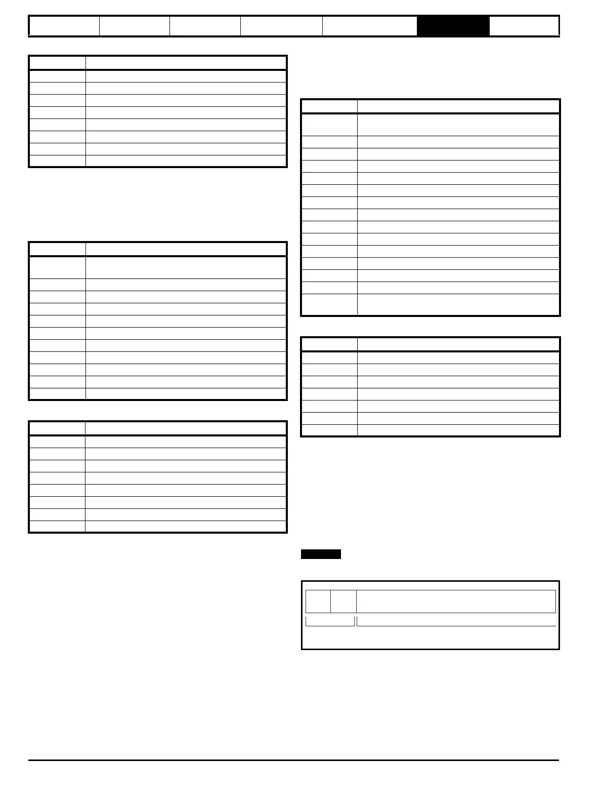
Table 6-4 Slave response
FC16 Write multiple
Writes a contiguous array of registers. The slave imposes an upper limit
on the number of registers which can be written. If this is exceeded the
slave will discard the request and the master will time out.
Table 6-5 Master request
Table 6-6 Slave response
FC23 Read/Write multiple
Writes and reads two contiguous arrays of registers. The slave imposes
an upper limit on the number of registers which can be written. If this is
exceeded the slave will discard the request and the master will time out.
Table 6-7 Master request
Table 6-8 Slave response
6.2.7 Extended data types
Standard MODBUS registers are 16bit and the standard mapping maps
a single #X.Y parameter to a single MODBUS register. To support 32bit
data types (integer and float) the MODBUS multiple read and write
services are used to transfer a contiguous array of 16bit registers.
Slave devices typically contain a mixed set of 16bit and 32bit registers.
To permit the master to select the desired 16bit or 32bit access the top
two bits of the register address are used to indicate the selected data
type.
The selection is applied for the whole block access.
Byte Description
0 Slave source node address
1 Function code 0x06
2 Register address MSB
3 Register address LSB
4 Register data MSB
5 Register data LSB
6 CRC LSB
7 CRC MSB
Byte Description
0
Slave node address 1 through 247,
0 is global
1 Function code 0x10
2 Start register address MSB
3 Start register address LSB
4 Number of 16bit registers MSB
5 Number of 16bit registers LSB
6 Length of register data to write (in bytes)
7 Register data 0 MSB
8 Register data 0 LSB
7+byte count CRC LSB
8+byte count CRC MSB
Byte Description
0 Slave source node address
1 Function code 0x10
2 Start register address MSB
3 Start register address LSB
4 Number of 16bit registers written MSB
5 Number of 16bit registers written LSB
6 CRC LSB
7 CRC MSB
Byte Description
0
Slave node address 1 through 247
0 is global
1 Function code 0x17
2 Start register address to read MSB
3 Start register address to read LSB
4 Number of 16bit registers to read MSB
5 Number of 16bit registers to read LSB
6 Start register address to write MSB
7 Start register address to write LSB
8 Number of 16bit registers to write MSB
9 Number of 16bit registers to write LSB
10 Length of register data to write (in bytes)
11 Register data 0 MSB
12 Register data 0 LSB
11+byte count CRC LSB
12+byte
count
CRC MSB
Byte Description
0 Slave source node address
1 Function code 0x17
2 Length of register data in read block (in bytes)
3 Register data 0 MSB
4 Register data 0 LSB
3+byte count CRC LSB
4+byte count CRC MSB
NOTE
bit 15
TYP1
bits 0 - 13
Type select Parameter address
X x 100+Y-1
bit 14
TYP0

Table of Contents

Question and Answer IconNeed help?

Do you have a question about the Control Techniques Mentor MP and is the answer not in the manual?

Control Techniques Mentor MP Specifications

General IconGeneral
Control MethodDigital
Control ModesSpeed, Torque
Communication OptionsRS485, CANopen, Ethernet
Protection ClassIP20
FeedbackEncoder
Protection FeaturesOvercurrent, Overvoltage, Undervoltage, Overtemperature, Field loss
Enclosure RatingIP20

Summary

General Information

Drive firmware version

Information about the drive's current firmware version and compatibility.

Environmental statement

Commitment to minimizing environmental impacts and EMS certification.

REACH legislation

Information on the REACH regulation regarding substances of very high concern.

Parameter Structure

Menu 0 (sub block)

Accessing Menu 0 in sub-block mode and customization options.

Pre-defined sub blocks

Details on pre-defined sub blocks and their enable/disable parameters.

Menu 0 (linear)

Description of Menu 0 when accessed in linear mode.

Advanced menus

Overview of advanced menus and keypad compatibility.

Solutions Modules

Recognition and configuration of Solutions Modules.

Menu 1: Speed reference

Analog reference

Configuration of analog inputs for speed reference.

Preset reference

Setup of preset speed references and selectors.

Keypad reference

Using the keypad for speed reference input.

Precision reference

High-resolution speed reference using precision settings.

Menu 2: Ramps

Acceleration rate selector

Selection of acceleration rates for drive control.

Deceleration rate selector

Selection of deceleration rates for drive control.

S ramp enable

Enabling and configuring S-shaped ramp profiles.

Menu 3: Speed feedback and speed control

Speed accuracy and resolution

Details on speed accuracy and resolution for different feedback types.

Analog feedback resolution

Resolution of armature voltage and tachometer feedback.

Menu 4: Torque and current control

Current measurement

Parameters related to current measurement and magnitude.

Overload detection

Configuration for overload detection and thermal protection.

Menu 5: Motor and field control

Armature control logic diagram

Logic diagram for armature control functions.

Field weakening enable

Enabling and configuring field weakening for motor control.

Menu 6: Sequencer and clock

Start/stop logic select

Selecting the logic for start and stop commands.

Enable stop key

Permanently enabling the stop key function.

Menu 7: Analog I/O

Hardware

Description of analog input and output terminals.

Update rate

Information on analog input and output sampling rates.

Menu 8: Digital I/O

I/O state

Sample rates and functions for digital I/O terminals.

I/O polarity select

Changing logic polarity for digital inputs and outputs.

Menu 9: Programmable logic, motorized pot and binary sum

Logic block functions

Description of logic block functions (AND, OR, XOR, Flip-flops).

Motorized pot function

Configuration of the motorized potentiometer function.

Menu 10: Status and trips

Drive OK

Indicates the drive is not in a trip state.

Overload alarm

Alarm triggered by high drive output current.

Menu 11: General drive setup

Parameter scaling

Scaling of parameter values for keypad display.

Serial address

Defining the unique address for the drive's serial interface.

Menu 12: Threshold detectors, variable selectors and brake control function

Threshold detectors function

Logic signals based on variable value comparison to thresholds.

Variable selectors function

Selecting or combining input parameters for output.

Brake control function

Control of an electro-mechanical brake via drive digital I/O.

Menu 13: Position control

Position control reference position

Defining the position reference from various sources.

Position control feedback position

Selecting the source for position feedback.

Menu 14: User PID controller

PID main reference source

Selecting the source for the PID controller's main reference.

PID feedback source

Selecting the source for the PID controller's feedback.

Menus 15, 16 and 17: Solutions Module slots

Solutions Module ID

Identifies the type of Solutions Module installed in a slot.

Solutions Module error status

Status of any errors detected in the Solutions Module.

Menu 18: Application menu 1

Application menu 1 power-down saved integer

Application menu 1 integer parameter saved on power-down.

Menu 19: Application menu 2

Application menu 2 power-down saved integer

Application menu 2 integer parameter saved on power-down.

Menu 20: Application menu 3

Application menu 3 read-write integer

Application menu 3 integer parameter that can be read/written.

Menu 21: Second motor parameters

Maximum reference clamp

Sets the maximum limit for the speed reference.

Minimum reference clamp

Sets the minimum limit for the speed reference.

Menu 23 Header definitions

Sub block headers

Defines the header parameters for Menu 0 sub blocks.

Pre-Defined Sub Blocks

Lists the pre-defined sub blocks and their corresponding Menu 0 parameters.

Serial Communications Protocol

6.1 ANSI communications protocol

Details the ANSIx3.28 communication protocol implementation for Mentor MP.

6.2 CT Modbus RTU specification

Describes the adaptation of the MODBUS RTU protocol for Control Techniques products.

Performance

7.1 Digital speed reference

Accuracy and resolution for digital speed references.

7.2 Analog reference

Update rates for analog reference inputs.

7.3 Analog outputs

Resolution and update rates for analog outputs.

7.4 Digital inputs and outputs

Response times for digital inputs and outputs.

7.5 Current feedback

Accuracy and resolution of current feedback.

7.6 Bandwidth

Speed and current loop bandwidth specifications.

Related product manuals