Parameter structure Keypad and display Parameter x.00
Parameter description
format
Advanced parameter
descriptions
Serial comms
protocol
Performance
Mentor MP Advanced User Guide 15
Issue Number: 4 www.controltechniques.com
3 Parameter x.00
Parameter x.00 is available in all menus and has the following functions.
*These functions do not require a drive reset to become active. All other
functions require a drive reset.
3.1 Parameter x.00 reset
When an action is started by setting Pr x.00 to one of the above values
and initiating a drive reset this parameter is cleared when the action is
completed successfully. If the action is not started, e.g. because the
drive is enabled and an attempt is made to load defaults, etc., Pr x.00 is
not cleared and no trip is produced. If the action is started and then fails
for some reason a trip is always produced and Pr x.00 is not cleared.
It should be noted that parameter saves etc. can also be initiated with
the copying parameter (Pr 11.42 (SE09, 0.30)). If actions that can be
initiated by either parameter are started and then completed
successfully Pr x.00 is cleared and Pr 11.42 (SE09, 0.30) is cleared if it
has a value of less than 3.
It should be noted that there could be some conflict between the actions
of Pr x.00 and Pr 11.42 (SE09, 0.30) Parameter copying when the drive
is reset. If Pr 11.42 (SE09, 0.30) has a value of 1 or 2 and a valid action
is required from the value of Pr x.00 then only the action required by
Pr x.00 is performed. Pr x.00 and Pr 11.42 (SE09, 0.30) are then reset to
zero. If Pr 11.42 (SE09, 0.30) has a value of 3 or 4 it will operate
correctly causing parameters to be save to a SMARTCARD each time a
parameter save is performed.
3.2 Saving parameters in drive EEPROM
Drive parameters are saved to drive EEPROM by setting Pr x.00 to save
and initiating a drive reset. In addition to user save parameters. power
down save parameters are also saved by these actions and by changing
drive mode, but not by any other actions that result in parameters being
saved to drive EEPROM (i.e. loading defaults). Power down save
parameters are not saved at power down unless the drive is supplied
from a normal line power supply, and so this gives the user the option of
saving these parameters when required.
When the parameter save is complete Pr x.00 is reset to zero by the
drive. Care should be taken when saving parameters because this
action can take between 400 ms and several seconds depending on
how many changes are stored in the EEPROM. If the drive is powered
down during a parameter save, it is possible that data may be lost.
When the drive is operating from a normal line power supply then it will
stay active for a short time after the power is removed, however, if the
drive is being powered from a 24 V control supply, or it is being operated
from a low voltage battery supply, the drive will power down very quickly
after the supply is removed. The drive provides two features to reduce
the risk of data loss when the drive is powered down.
1. If Pr x.00 is set to save a parameter save is only initiated on drive
reset if the drive is supplied from a normal line power supply
(Pr 10.16 = 0 and Pr 6.44 = 0).
2. Two banks of arrays are provided in EEPROM to store the data.
When a parameter save is initiated the data is stored in a new bank
and only when the data store is complete does the new bank
become active. If the power is removed before the parameter save is
complete a SAVE.Er trip (user save parameter save error) or
PSAVE.Er trip (power down save parameter save error) will be
produced when the drive is powered up again indicating that the
drive has reverted to the data that was saved prior to the last
parameter save.
The second feature will significantly reduce the possibility of completely
invalidating all saved data, which would result in an EEF trip on the next
power-up. However the following points should be noted:
1. If the power is removed during a parameter save the current data
that is being saved to the EEPROM that is different from the last
data saved in the EEPROM will be lost and SAVE.Er or PSAVE.Er
trip will occur on power-up.
2. This feature does not apply when user save parameters are saved
automatically by adjusting the values in menu 0 with an LED keypad.
However, the time taken to save parameters in this way is very short,
and is unlikely to cause data loss if the power is removed after the
parameter has been changed. It should be noted that any parameter
changes made in this way are included in the currently active bank in
the EEPROM, so that if the power is removed during a subsequent
save initiated via Pr x.00 that results in an SAVE.Er trip, the changes
made via menu 0 will be retained and not lost.
3. User save parameters are saved to drive EEPROM after a transfer
of data from an electronic nameplate in an encoder.
4. User save parameters are saved to drive EEPROM after a transfer
of data from a SMARTCARD.
5. This feature is not provided for data saved to a SMARTCARD, and
so it is possible to corrupt the data files on a SMARTCARD if the
power is removed when data is being transferred to the card.
6. User save parameters are saved to drive EEPROM after defaults
are loaded.
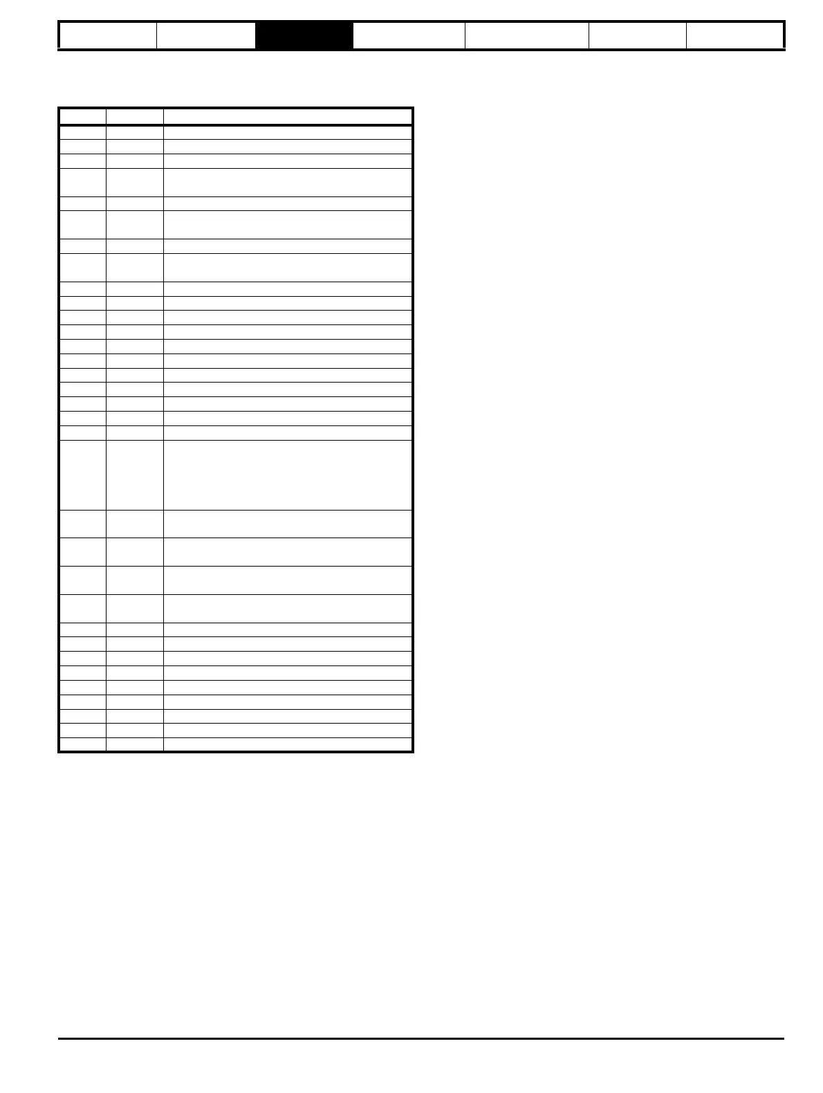
Value String Action
0 No Act No action
1 SAUE Save parameters
2 rEAd 1* Transfer SMARTCARD data block 1 to the drive
3PrOg 1*
Transfer drive parameters as difference from
default to SMARTCARD block number 1
4 rEAd 2* Transfer SMARTCARD data block 2 to the drive
5PrOg 2*
Transfer drive parameters as difference from
default to SMARTCARD block number 2
6 rEAd 3* Transfer SMARTCARD data block 3 to the drive
7PrOg 3*
Transfer drive parameters as difference from
default to SMARTCARD block number 3
8 diS.diFF Display non-default values only
9 diS.dESt Display destination parameters only
10 Eur Load European defaults
11 USA Load USA defaults
12 rES OP Reset all Solution Modules
1000 1000 Save parameters
1070 1070 Reset all Solution Modules
1233 1233 Load European defaults
1244 1244 Load USA defaults
1255 1255 Load European defaults (excluding menus 15 to 20)
1256 1256 Load USA defaults (excluding menus 15 to 20)
2001 2001*
Transfer drive parameter to a card and create a
bootable difference from default SMARTCARD
block with data block number 1 and clear
parameter 11.42. If data block 1 exists it is over
written.
3yyy 3yyy*
Transfer drive parameters to SMARTCARD block
number yyy
4yyy 4yyy*
Transfer drive parameters as difference from
default to SMARTCARD block number yyy
5yyy 5yyy*
Transfer Onboard Applications Lite ladder
program to SMARTCARD block number yyy
6yyy 6yyy*
Transfer SMARTCARD data block yyy to the
drive
7yyy 7yyy* Erase SMARTCARD data block yyy
8yyy 8yyy* Compare drive data with SMARTCARD block yyy
9555 9555* Clear SMARTCARD warning suppression flag
9666 9666* Set SMARTCARD warning suppression flag
9777 9777* Clear SMARTCARD read-only flag
9888 9888* Set SMARTCARD read-only flag
9999 9999* Erase SMARTCARD
12000** 12000** Display non-default values only
12001** 12001** Display destination parameters only