Menus 15 to 17
Parameter
structure
Keypad and
display
Parameter x.00
Parameter description
format
Advanced parameter
descriptions
Serial comms
protocol
Performance
186 Mentor MP Advanced User Guide
www.controltechniques.com Issue Number: 4
5.16 Menus 15, 16 and 17: Solutions Module slots
Pr x.00 and Pr x.01 are always present in menus 15, 16 and 17. Pr x.01 indicates which type of module is present (0 = no module installed). When a
module is installed the drive provides the relevant menu (menu 15 for slot 1, 16 for slot 2 and 17 for slot 3) depending on the Solutions Module
installed. The possible categories are shown below.
Refer to the specific Solutions Module User Guide for more information.
Most modules include a processor and parameters are updated by the processor in the Solutions Module. However, dumb modules do not contain a
processor and all parameters are updated by the drive processor.
Dumb Solutions Module parameters are read/written by the drive background task or at the combined update time for time critical parameters. The
combined update time depends on the number and type of dumb Solutions Modules installed to the drive. For each Solutions Module the update rate
of these parameters is specified as 4 ms, 8 ms, etc. The combined update time is the total of the update times for all dumb Solutions Modules
installed.
For example, if a module with 4 ms update time and a module with 8 ms are installed to the drive, then the combined update time for the time critical
parameters of each module is 12 ms.
In the parameter tables the update time added by the type of module is given, for example 4 ms for the SM-Encoder Plus or 8 ms for the SM-I/O Plus.
When parameters are saved by the user in the drive EEPROM the option code of the currently installed module is saved in EEPROM. If the drive is
subsequently powered-up with a different module installed, or no module installed where a module was previously installed, the drive gives a Slot.dF
trip. The menu for the relevant slot appears for the new module category with the default parameter values for the new category. The new parameters
values are not stored in EEPROM until the user performs a parameter save.
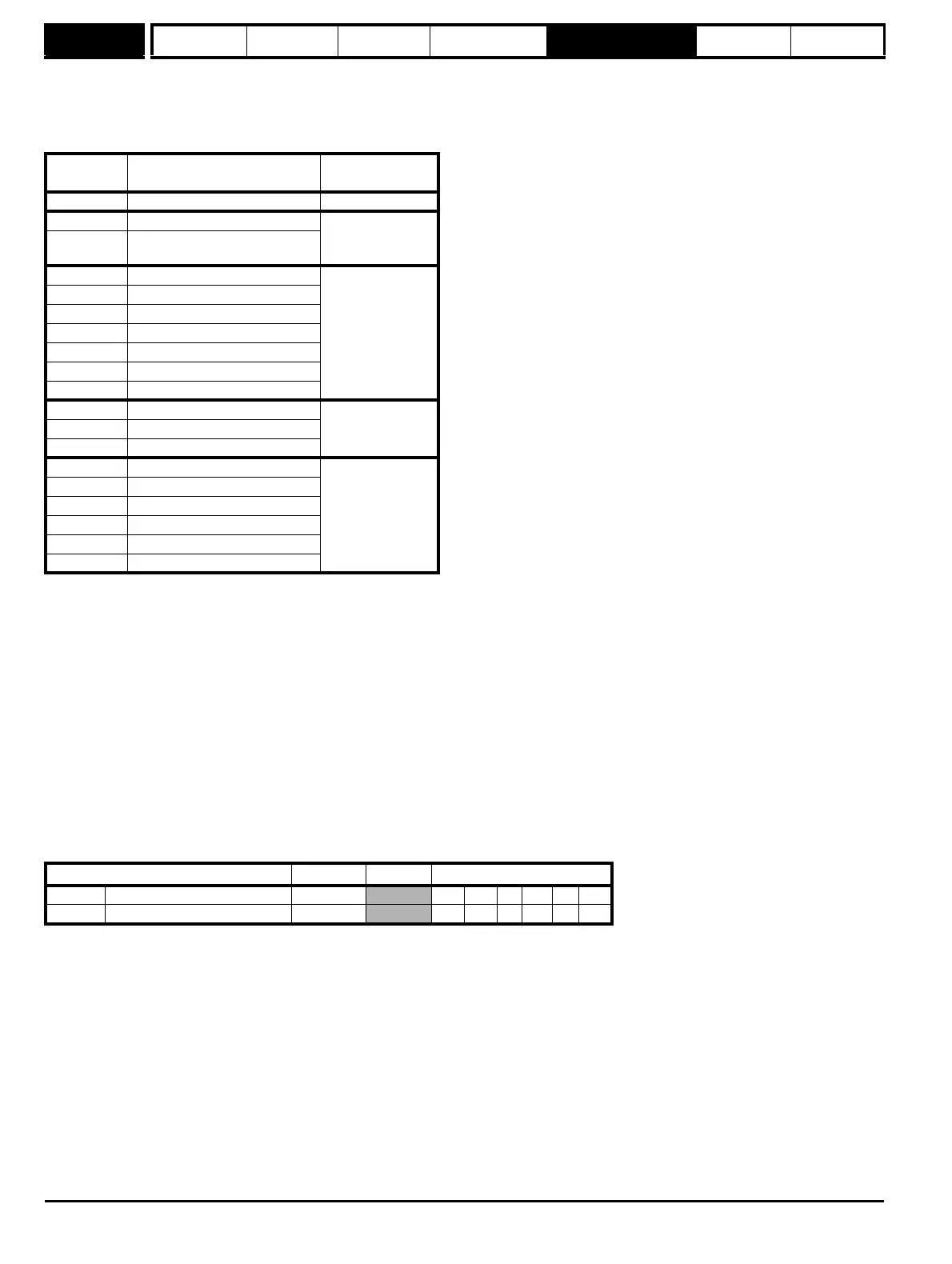
Parameters common to all categories
Solutions
Module ID
Module Category
0 No module installed
102 SM-Universal Encoder Plus
Feedback
104
SM-Encoder Plus and SM-
Encoder Output Plus
201 SM-I/O Plus
Automation
(I/O Expansion)
203 SM-I/O Timer
204 SM-I/O PELV
205 SM-I/O24V Protected
206 SM-I/O120V
207 SM-I/O Lite
208 SM-I/O 32
304 SM-Applications Plus
Automation
(Applications)
305 SM-Applications Lite V2
306 SM-Register
403 SM-PROFIBUS DP-V1
Fieldbus
404 SM-INTERBUS
407 SM-DeviceNet
408 SM-CANopen
410 SM-Ethernet
421 SM-EtherCAT
Parameter Range Default Type
x.01 Solutions Module ID 0 to 599
RO Uni PT US
x.50 Solutions Module error status 0 to 255
RO Uni NC PT