Menu 21
Parameter
structure
Keypad and
display
Parameter x.00
Parameter description
format
Advanced parameter
descriptions
Serial comms
protocol
Performance
190 Mentor MP Advanced User Guide
www.controltechniques.com Issue Number: 4
5.20 Menu 21: Second motor parameters
The following parameters are used instead of the normal motor setup parameters when Pr 11.45 = 1.
When the alternative parameter set is being used by the drive, the decimal point second from the right in the first row is on.
For more information about a particular parameter, see the equivalent normal motor map 1 parameter.
* The range shown for Pr 21.02 shows the range used for scaling purposes (i.e. for routing to an analog output etc.). Further range restrictions are
applied as shown below:
Unlike the motor 1 (Pr 1.14= {SE05, 0.26}) this parameter is not used for T28 and T29 digital input auto-selection (see Pr 8.52 on page 121).
Pr 21.03 defines how the value of Pr 1.49 is derived as follows:
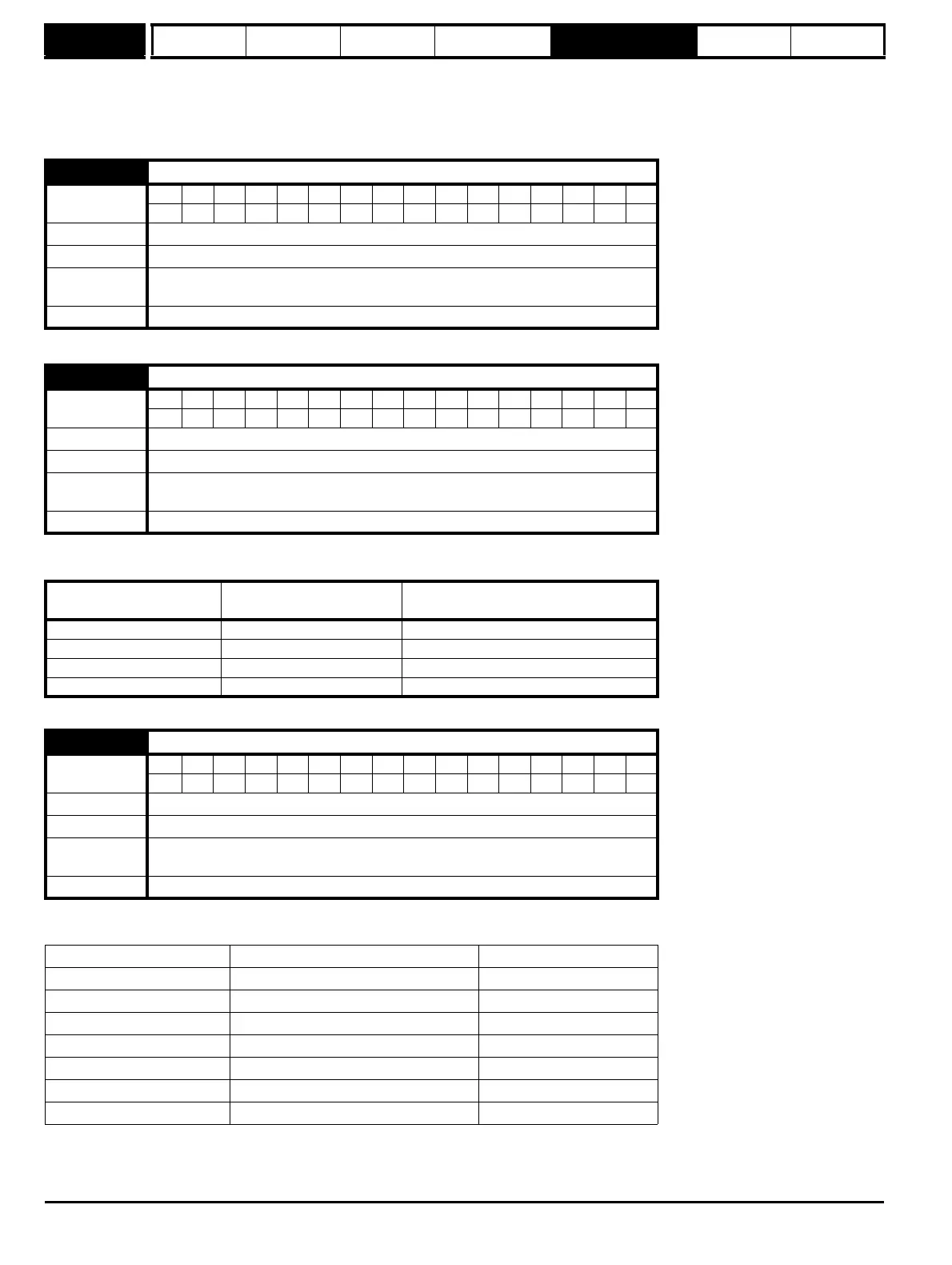
21.01 Maximum reference clamp
Coding
Bit SP FI DE Txt VM DP ND RA NC NV PT US RW BU PS
1111
Range SPEED_LIMIT_MAX rpm
Default 1000
Normal
parameter
Pr 1.06 = {SE02, 0.23}
Update rate Background read
21.02 Minimum reference clamp
Coding
Bit SP FI DE Txt VM DP ND RA NC NV PT US RW BU PS
1111
Range -SPEED_LIMIT_MAX to SPEED_LIMIT_MAX rpm*
Default 0.0
Normal
parameter
Pr 1.07 = {SE01, 0.22}
Update rate Background read
Pr 1.08
(Neg min ref enable)
Pr 1.10
(Bipolar mode enable)
Range
0 0 0 to 21.01
01 0
1 0 -SPEED_LIMIT_MAX to 0 rpm
1 1 -SPEED_LIMIT_MAX to 0 rpm
21.03 Reference selector
Coding
Bit SP FI DE Txt VM DP ND RA NC NV PT US RW BU PS
1111
Range 0 to 6
Default 0 (A1.A2)
Normal
parameter
Pr 1.14= {SE05, 0.26}
Update rate 4 ms read
Value of Pr 21.03 Display String Pr 1.49
0 A1.A2 *Selected by terminal input
1A1.Pr1
2A2.Pr2
3Pr3
4Pad4
5Prc5
6 Keypad ref only 6