Parameter structure Keypad and display Parameter x.00
Parameter description
format
Advanced parameter
descriptions
Serial comms
protocol
Performance
Mentor MP Advanced User Guide 209
Issue Number: 4 www.controltechniques.com
The 2bit type field selects the data type according to the table below:
If a 32bit data type is selected then the slave uses two consecutive 16bit
MODBUS registers (in 'big endian'). The master must also set the
correct 'number of 16bit registers'.
Example, read #20.21 through #20.24 as 32bit parameters using FC03
from node 8:
Table 6-9 Master request
Table 6-10 Slave response
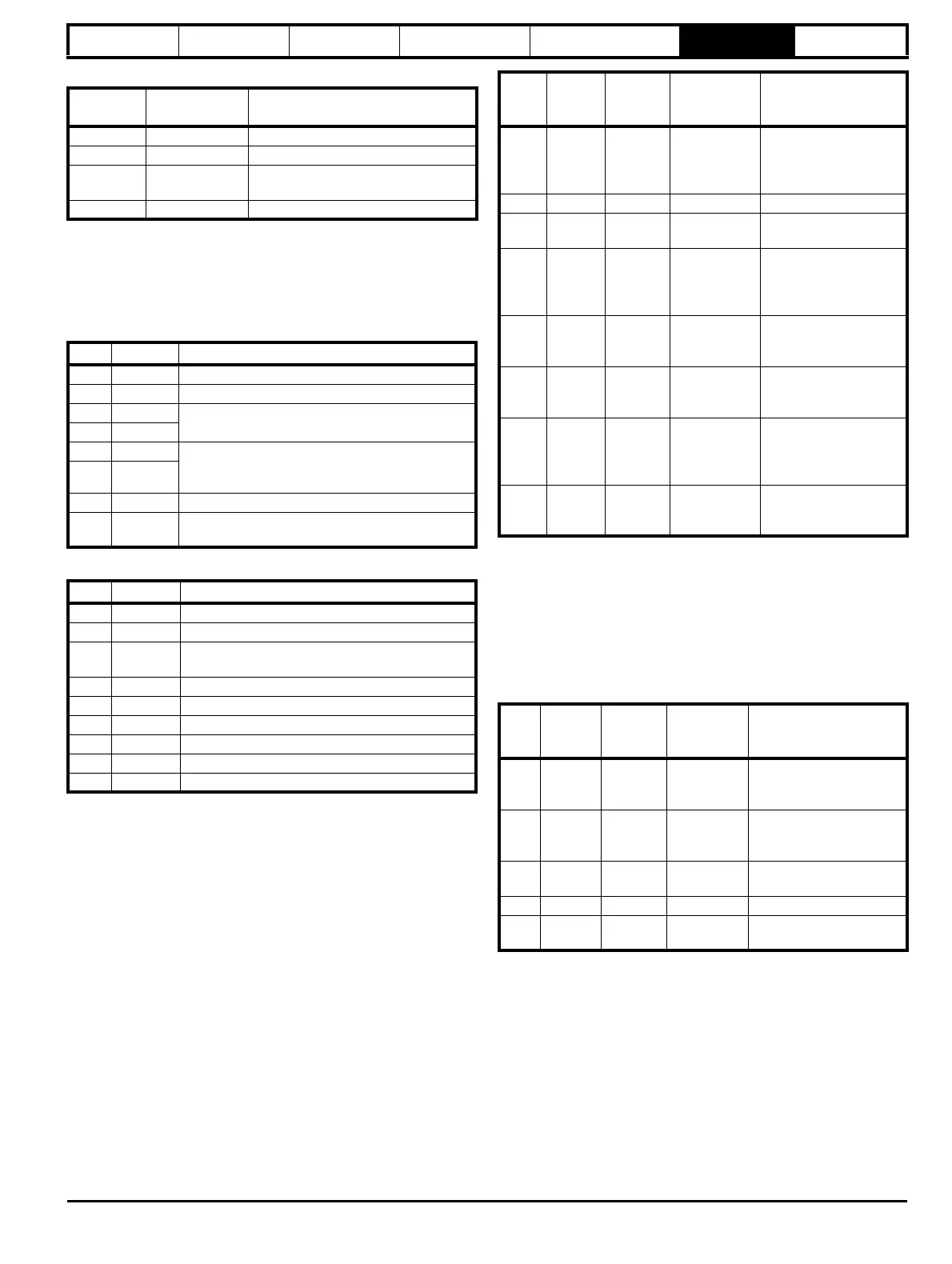
Reads when actual parameter type is different from
selected
The slave will send the least significant word of a 32 bit parameter if that
parameter is read as part of a 16 bit access.
The slave will sign extend the least significant word if a 16 bit parameter
is accessed as a 32 bit parameter. The number of 16 bit registers must
be even during a 32 bit access.
Example, If #1.28 is a 32 bit parameter with a value of 0x12345678,
#1.29 is a signed 16 bit parameter with a value of 0xABCD, and #1.30 is
a signed 16 bit parameter with a value of 0x0123.
Writes when actual parameter type is different from
selected
The slave will allow writing a 32 bit value to a 16 bit parameter as long as
the 32 bit value is within the normal range of the 16 bit parameter.
The slave will allow a 16 bit write to a 32 bit parameter. The slave will
sign extend the written value, therefore, the effective range of this type of
write will be ±32767.
Examples, if #1.28 has a range of ±100000, and #1.29 has a range of
±10000.
6.2.8 Exceptions
The slave will respond with an exception response if an error is detected
in the master request. If a message is corrupted and the frame is not
received or the CRC fails then the slave will not issue an exception. In
this case the master device will time out. If a write multiple (FC16 or
FC23) request exceeds the slave maximum buffer size then the slave
will discard the message. No exception will be transmitted in this case
and the master will time out.
Type field
bits 15-14
Selected data
type
Comments
00 INT16 backward compatible
01 INT32
10 Float32
IEEE754 standard
Not supported on all slaves
11 Reserved
Byte Value Description
0 0x08 Slave destination node address
1 0x03 FC03 multiple read
20x47
Start register address #20.21
(16384 + 2021 - 1) = 18404 = 0x47E4
30xE4
4 0x00 Number of 16bit registers to read
#20.21 through #20.24 is 4x32bit registers =
8x16bit registers
50x08
6 CRC LSB
7
CRC
MSB
Byte Value Description
0 0x08 Slave destination node address
1 0x03 FC03 multiple read
20x10
Length of data (bytes) = 4x32bit registers =
16bytes
3-6 #20.21 data
7-10 #20.22 data
11-14 #20.23 data
15-18 #20.24 data
19 CRC LSB
20 CRC MSB
Read
Start
register
address
Number
of 16bit
registers
Response Comments
#1.28 127 1 0x5678
Standard 16 bit access
to a 32bit register will
return low 16bit word of
truncated data
#1.28 16511 2 0x12345678 Full 32bit access
#1.28 16511 1 Exception 2
Number of words must
be even for 32bit access
#1.29 128 1 0xABCD
Standard 16 bit access
to a 32bit register will
return low 16bit word of
data
#1.29 16512 2 0xFFFFABCD
32bit access to a 16bit
register will return 32bit
sign extended data
#1.30 16513 2 0x00000123
32bit access to a 16bit
register will return 32bit
sign extended data
#1.28
-
#1.29
127 2
0x5678,
0xABCD
Standard 16 bit access
to a 32bit register will
return low 16bit word of
truncated data
#1.28
-
#1.29
16511 4
0x12345678,
0xFFFFABCD
Full 32bit access
Write
Start
register
address
Number
of 16bit
registers
Data Comments
#1.28 127 1 0x1234
Standard 16 bit write to a
32bit register. Value
written = 0x00001234
#1.28 127 1 0xABCD
Standard 16 bit write to a
32bit register. Value
written = 0xFFFFABCD
#1.28 16511 2 0x00001234
Value written =
0x00001234
#1.29 128 1 0x0123 Value written = 0x0123
#1.29 16512 2 0x00000123
Value written =
0x00000123