Parameter
structure
Keypad and
display
Parameter x.00
Parameter description
format
Advanced parameter
descriptions
Serial comms
protocol
Performance
Menu 3
Mentor MP Advanced User Guide 55
Issue Number: 4 www.controltechniques.com
The input electronics for the tachometer input can be configured in 3 ways.
If the encoder has been incorrectly wired this bit can be used to correct the encoder feedback.
0 - Clockwise
1 - Anti clockwise
When this bit is set the speed feedback source is automatically changed to estimated speed feedback when the selected speed feedback is lost.
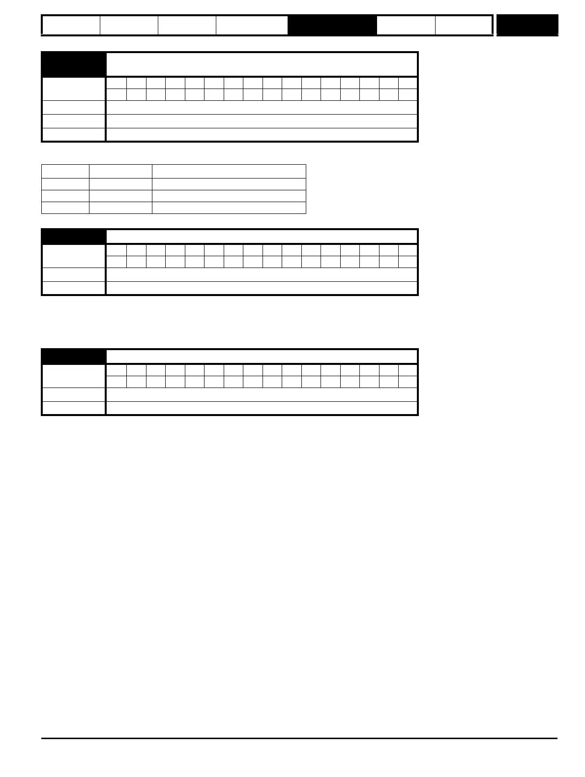
3.53
{Fb03, 0.73}
Tachometer input mode
Coding
Bit SP FI DE Txt VM DP ND RA NC NV PT US RW BU PS
111
Range 0 to 2
Default 0 (DC)
Update rate Background read
Value Text Action
0 DC DC tachometer
1 DC Filt DC tachometer with input filter
2 AC AC tachometer
3.54
Encoder direction
Coding
Bit SP FI DE Txt VM DP ND RA NC NV PT US RW BU PS
111
Default 0
Update rate Background read
3.55
Select estimated speed on feedback loss
Coding
Bit SP FI DE Txt VM DP ND RA NC NV PT US RW BU PS
111
Default 0
Update rate Background read