EasyManua.ls Logo

Control Techniques UD70 User Manual

Control Techniques UD70
154 pages
To Next Page IconTo Next Page
To Previous Page IconTo Previous Page
Page #127 background imageLoading...
Page #127 background image
UD70
Issue code: 70nu2
Features 8-29
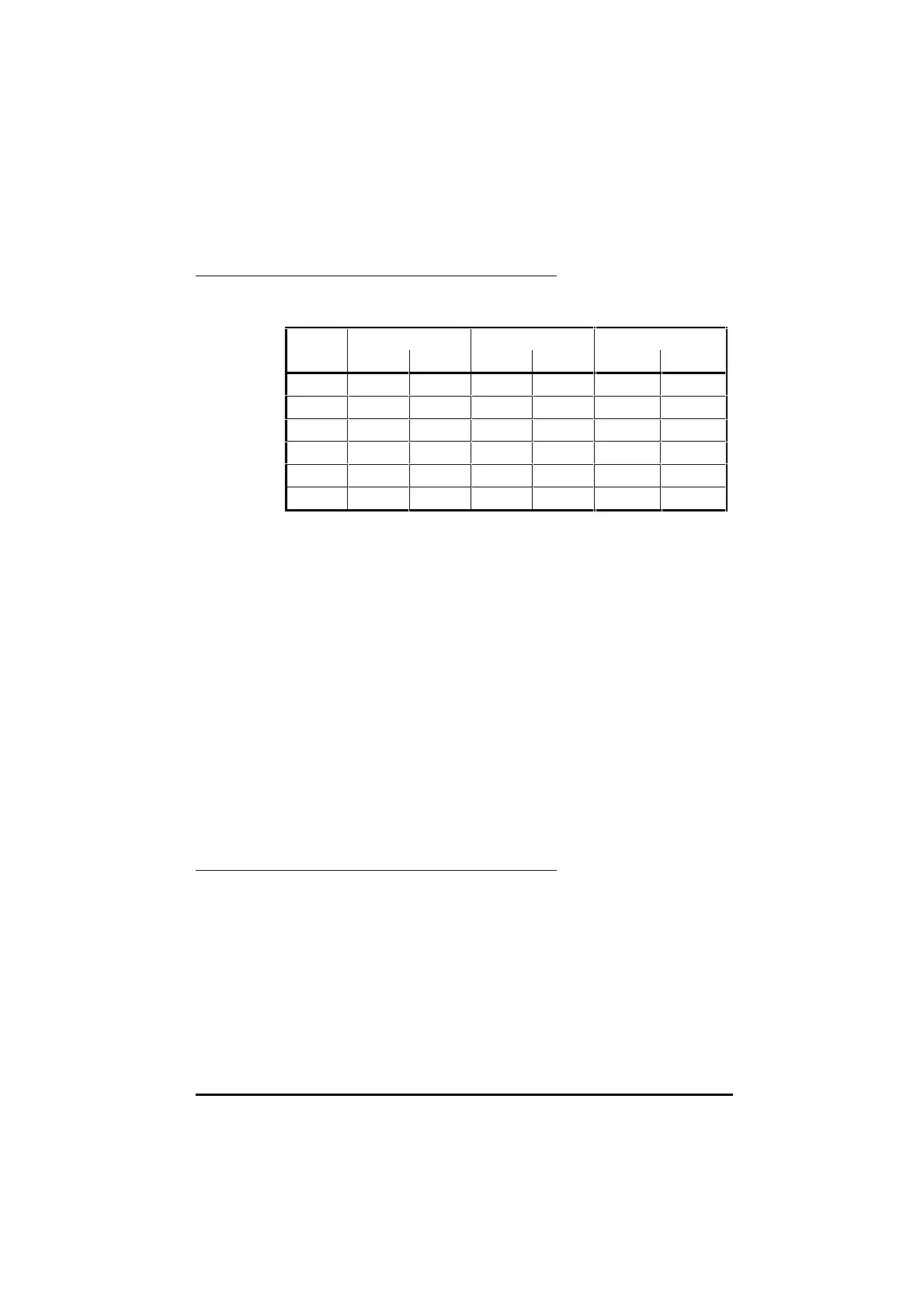
Building the cam table
The cam positions at the beginning and end of each section can be
determined from the profile.
Section Master Slave Position Change
Start Finish Start Finish master% slave%
1 0 20000 0 5000 20000 5000
2 20000 25000 5000 20000 5000 15000
3 25000 35000 20000 20000 10000 0
4 35000 50000 20000 -10000 15000 -30000
5 50000 70000 -10000 -10000 20000 0
6 70000 80000 -10000 0 10000 10000
The last two columns produce the values required for each array. The arrays
can be defined as follows:
CONST master%{
20000,5000,10000,15000,20000,10000
}
CONST slave%{
5000, 15000,0,-30000,0,10000
}
If the slave must always return to the same position at the end of each cam
cycle, the sum of all the slave array elements must be 0. An easy way to do
this is to construct the array using a spreadsheet, and copy and paste the
series of numbers into the DPL editor.
When the cam is called in the DPL program, the following command line
would be used.
setup% = CAMINIT(master%, slave%, 6, 0, 0)
Re-defining the Cam Table
The cam table can be re-defined from a DPL program at any time. Cam
control must be deselected (_Q32%.4 reset to 0) before the CAMINIT
function can be called again. Any combination of arrays can be used,
provided they have previously been defined, and both arrays contain at least
the stated number of cam points.

Table of Contents

Other manuals for Control Techniques UD70

Question and Answer IconNeed help?

Do you have a question about the Control Techniques UD70 and is the answer not in the manual?

Control Techniques UD70 Specifications

General IconGeneral
BrandControl Techniques
ModelUD70
CategoryControl Unit
LanguageEnglish

Summary

Safety Information

General Information

Introduction to UD70 and DPL Toolkit

UD70 Overview and DPL Toolkit Basics

Explains the UD70 as a microcomputer for Unidrive flexibility and the DPL Toolkit for software development.

UD70 Memory and PC Requirements

Details UD70 memory storage and minimum PC specifications for DPL Toolkit.

Technical Data and User Knowledge

Lists UD70 technical specifications and assumes basic Windows knowledge for users.

Installation and Configuration

Installation Procedure

Instructions for physically fitting the UD70 module into the Unidrive.

System Configuration and DPL Toolkit Setup

Details host PC connections (RS232) and installing the DPL Toolkit.

DPL Toolkit Operations

DPL Toolkit Overview and File Management

Introduces the DPL Toolkit's capabilities and file handling procedures.

Editing Programs and Applying Styles

Covers editing code, using styles, and auto-indent features within the DPL Toolkit.

Compiling and Running Programs

Details the process of compiling DPL programs and executing them on the UD70.

Serial Communications

Serial Communications Introduction

Explains serial communication links using RS485 for UD70 systems.

Hardware Connections and ANSI Protocol

Details RS485 hardware connections, ANSI communications fundamentals, and frames.

Serial Modes and ANSI Instructions

Outlines various RS485 modes and available ANSI instructions for communication.

Reference Guide

UD70 Tasks and Programming Structures

Explains different task types (INITIAL, BACKGROUND, CLOCK) and their roles in UD70 programming.

DPL Instructions and Functions Reference

Details various DPL programming instructions and mathematical/signal-processing functions.

UD70 Features

PLC Parameters and Feature Introduction

Introduces PLC parameters and the UD70's advanced position control and profile generation capabilities.

Encoder Lines, Position, and Controller Setup

Explains encoder line units, position calculation, and enabling the position controller.

Default Values and Parameter Descriptions

Details default reset values and provides descriptions for various UD70 parameters.

Logic Diagrams and Digital Lock Control

Illustrates logic diagrams for position control and explains digital lock functions.

Cam Function and Reference Switching

Describes the cam function for slave axis control and switching between control modes.

Timer/Counter Unit and Digital I/O Ports

Details the UD70's timer/counter unit and digital I/O port functionality.

Memory Storage and RS232 Communications

Covers non-volatile memory storage and using the RS232 port for Drive-to-Drive communication.

Diagnostics and Error Handling

Run-time Errors and Trip Codes

Explains run-time errors, their causes, and provides a list of trip codes with their actions.

Compiler Errors and Advanced Error Handling

Lists compiler error messages and details advanced error handling using the ERROR Task.

UD70 Parameters

Set-up Parameters and RS485 Modes

Details UD70 set-up parameters and the various RS485 port modes available.

Virtual Parameters and Control Words

Explains virtual parameters and the function of control and status words.

General-Purpose Parameters and I/O Box Configuration

Lists general-purpose parameters and details I/O box configuration through menus.

Related product manuals