5-28
Copyright 2017 Cummins Inc.
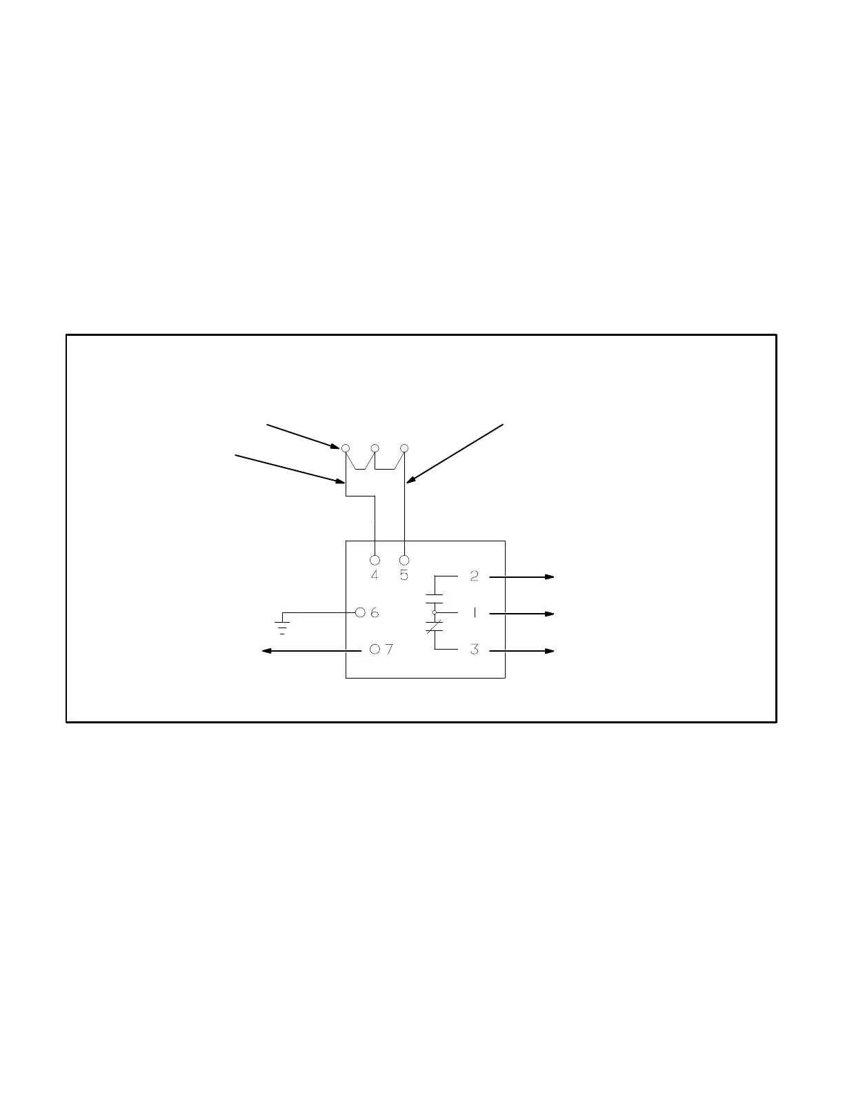
Thermistor Relay (Optional)
The optional thermistor relays are rail mounted in-
side the accessory box (Figure 5-3). Each relay
monitors three thermistors (one per phase) that are
connected in series inside the alternator. One se-
ries or chain of thermistors are rated at 140
C and
the other at 160
C. The 140 C relay is commonly
used in a pre-alarm circuit and the 160
C relay in a
shut-down circuit. The relay will energize (trip)
when the thermistor chain resistance reaches 3000
500 ohms.
The relay terminals 1, 2 and 3 are for customer con-
nection and are normally connected to a breaker
shunt trip or a load shed circuit (Figure 5-7).
The contacts are rated:
3 amps at 250 VAC
1 amp at 480 VAC
A40-TB1-4
(GROUND)
WHITE/RED
THERMISTORS
A BC
A40-TB1-2
(SWITCHED B+)
BLUE
FAULT CHANNELS
(CUSTOMER
CONNECTIONS)
RELAY CONTACTS
FIGURE 5-7. THERMISTOR RELAY (OPTIONAL)