3-12
Copyright 2017 Cummins Inc.
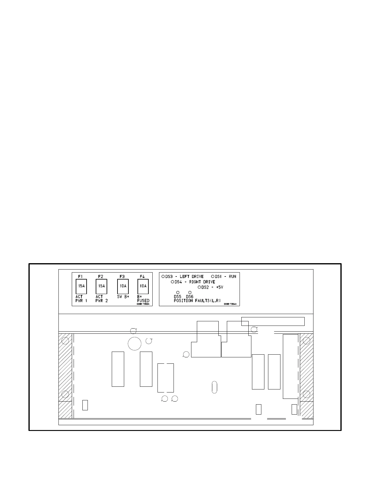
GOVERNOR OUTPUT MODULE (A38)
The governor output module (Figure 3-10) receives
a low power, 3 kHz pulse-width modulated (PWM)
command from the engine interface board (A31).
This module drives the two fuel actuators (right and
left) with a feed back-controlled, 200 Hz PWM pow-
er output stage. The governor module also has both
right and left 0-5 volt actuator position voltages
which are used for actuator diagnostics.
Connectors
The governor output module has two connectors.
They are:
J6
Inputs: Run Signal, B+, Governor Command (from
engine interface board)
Outputs: B+ (fused), SwB+, actuator position volt-
ages (R, L), and Rack Position Fault
J13
Inputs: (R, L) Actuator position sensing signals
Outputs: (R, L) Actuator drive
Fuses
The governor output module has four fuses to pro-
tect it from overloads and groundfaults. They are:
F1 Left Actuator Drive (15 Amps)
F2 Right Actuator Drive (15 Amps
)
F3 Switched B+ (10 Amps)
F4 B+ Fused (10 Amps)
LEDs
The governor output module has six LED’s that indi-
cate the following conditions:
DS1 (Green) Run command signaling governor
module is active.
DS2 (Green) 5 volt power supply is active.
DS3 (Green) Left actuator drive is active. The PCC
duty cycle range is 25 - 93%. When running,
the maximum duty cycle is about 63%. Note
that the brighter the LED, the larger the duty
cycle.
DS4 (Green) Right actuator drive is active. See
DS3 description.
DS5 (Red) Left actuator fault indicator. If the actua-
tor is more than 1.5 mm form its commanded
position, the fault indicator will be ON. Note
that the actuator has maximum range of 0 −
21mm. During transients and starting se-
quences, the fault indicator will become ac-
tive for short (200 millisecond) periods.
DS6 (Red) Right actuator fault indicator. See DS5
description.
RH
LOOP
LH
LOOP
DS3
DS4
DS5 DS6
F1 F2
R54
DS2
K1 K2
F3 F4
X1
R63
R68
DS1
BANK TO
BANK
FIGURE 3-10. GOVERNOR OUTPUT MODULE (A38)