5-1
Copyright 2017 Cummins Inc.
5. Control Service and Calibration
GENERAL
This section contains circuit board removal and re-
placement procedures, calibration procedures for
the generator set control and test procedures for the
alternator and engine components. Refer to the fig-
ures included with this information and also the Wir-
ing Diagrams section when instructed.
Before servicing the PCC, it is recommended that all
settings be recorded. This will make sure of correct
and complete readjustment of the PCC in the event
that all previous entries are lost during servicing.
CIRCUIT BOARD
REMOVAL/REPLACEMENT
No special tools (other than a grounding wrist strap)
are required to remove a circuit board from inside
the control panel or the accessory box.
There are several circuit boards, that when re-
placed, require you to recalibrate the control panel
functions. Table 5-1 lists the circuit boards and the
appropriate procedure to perform to recalibrate the
control panel. The circuit board locations are shown
in Figure 5-1.
Before you attempt to remove a circuit board, read
the Circuit Board Removal Safety Precautions in
this section.
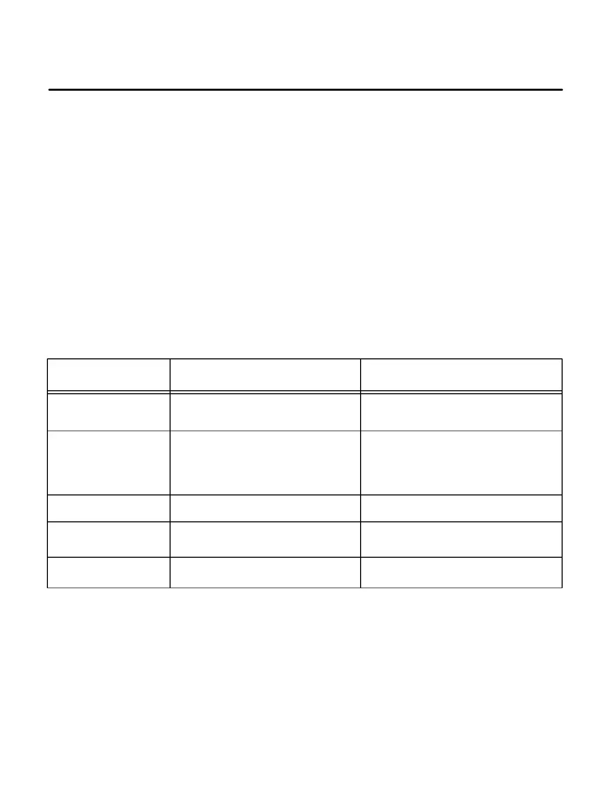
TABLE 5-1. CONTROL PANEL RECALIBRATION
CIRCUIT BOARD/
DEVICE
Analog Board (A33)
ADJUSTMENT PROCEDURE / PAGE
1. Voltage, Current and PF.
2. Coolant Temperature L & R
Digital Board (A32) Must recalibrate all values, starting with
the Initial Start Setup procedure.
1. Initial Start Setup (Page 5-4).
2. Adjust Menu (Page 5-6).
3. Setup and Calibration Menus (Page
5-8).
PT/CT Board (A36) Voltage, Current and PF.
Setup and Calibration Menus (Page 5-8)
Setup and Calibration Menus (Page 5-8)
Governor Output
Module (A38)
Torque Adjustment % DC Engine Torque Adjustment (Page 5-22)
Fuel Pump Torque Adjustment % DC Engine Torque Adjustment (Page 5-22)