3-3
Copyright 2017 Cummins Inc.
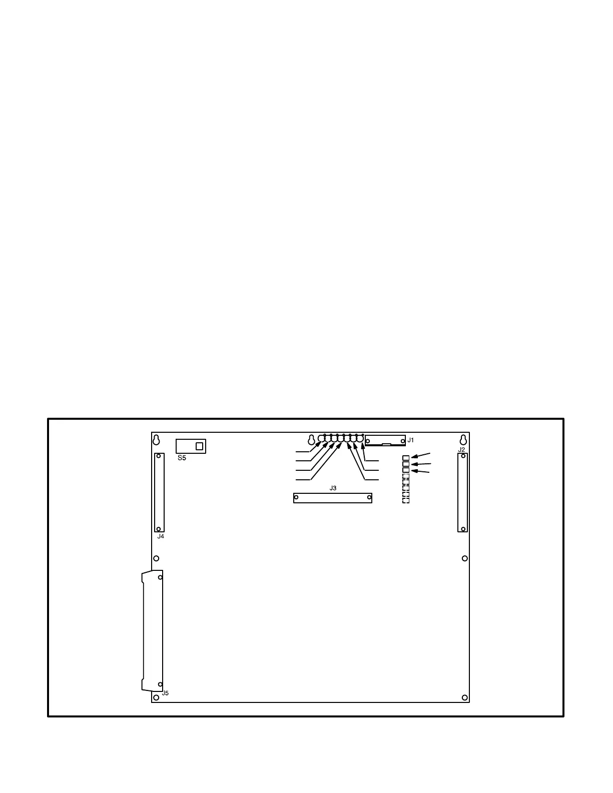
DIGITAL BOARD (A32)
The digital circuit board (Figure 3-3) contains the
microprocessor and the operational software for the
control. It connects to all other boards inside the
control. This board also provides the analog-to-digi-
tal conversions for the PCC.
Switch
S5 Slide the switch to the left to select the Power
On (awake) mode. Control panel power/oper-
ating software will remain on until the switch is
reset to the Standby mode. It is recom-
mended that switch S5 be left in the Power On
mode in all applications, except those where
auxiliary battery charging is not available.
Slide right to put the PCC in the Standby
(“sleep”) mode. In this mode, the PCC oper-
ating software will be initiated by selection of
Run on the front panel, by pressing the Self
Test switch, by a remote start input (in Auto
mode), or by any one of several “wake-up”
signals from external switches.
Connectors
The digital board has five connectors. They are:
J1 Serial Interface RS232
J2 Connects to J4 on A34 Customer Interface
board
J3 Connects to J2 on A33 Analog board
J4 Connects to J1 on A31 Engine Interface
board
J5 Connects to J5 on A35 Digital Display assem-
bly
LEDs
The digital board has seven LED’s that indicate the
following conditions:
DS1 Spare (Green)
DS2 Spare (Green)
DS3 +18 VDC supply OK (Green)
DS4 +5 VDC supply OK (Green)
DS5 Run (Flashes once per second if software
is running) (Green)
DS6 +24 VDC B+ supply OK (Green)
DS7 +12 VDC supply OK (Green)
Resistors
The three resistors (R36, R37 and R38) are used to
configure the digital board to the generator set mod-
el number. Refer to Digital Board (A32) Calibration
in Section 5, which provides a detailed description
of how to configure this board.
DS1
DS2
DS3
DS4
DS7
DS6
DS5
R36
R37
R38
FIGURE 3-3. DIGITAL BOARD (A32)