3-7
Copyright 2017 Cummins Inc.
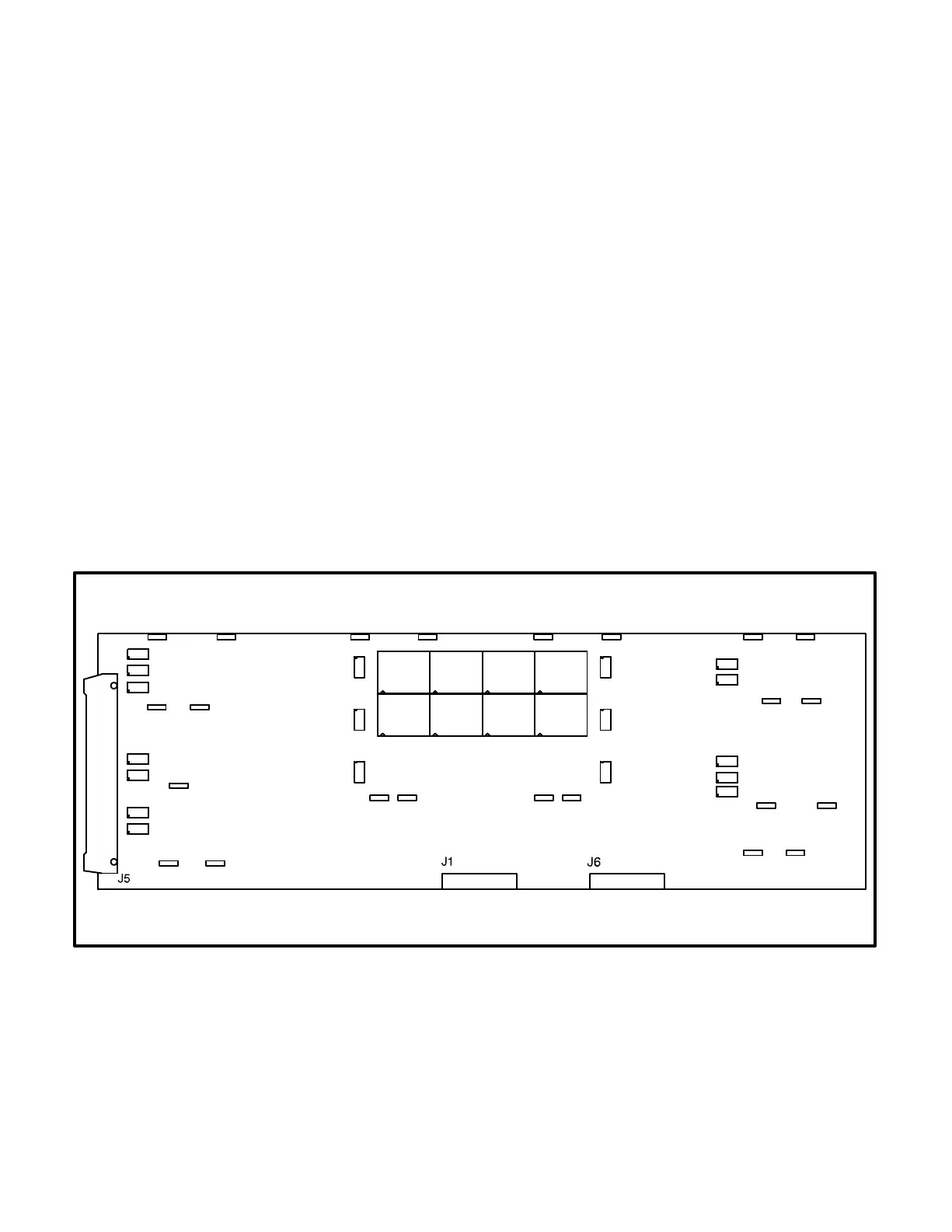
DIGITAL DISPLAY BOARD (A35)
The digital board (Figure 3-6) connects to all meters
and the LED display.
Connectors
The digital board has three connectors. They are:
J1 Connects to front panel membrane switches
J5 Connects to J2 on A32 Digital board. (With J5
disconnected, the display will be non-func-
tional, but the PCC will continue to operate.)
J6 Connects to meters, Run/Off/Auto switch, J3
on A31 Engine Interface board
LEDs
The digital board has 18 LED’s that are used to indi-
cate operational status of the generator set and
control panel mode/switch selections.
DS9 Not In Auto (Red)
DS10 Upper Scale (Green)
DS11 Left Top Arrow (Green)
DS12 Right Top Arrow (Green)
DS13 Warning (Amber)
DS14 Lower Scale (Green)
DS15 Shutdown (Red)
DS20 Left Bottom Arrow (Green)
DS21 Right Bottom Arrow (Green)
DS22 Automatic mains failure (AMF) for parallel-
ing application only: Breaker Closed (Red)
DS23 Phase A (Green)
DS24 Reset Arrow (Green)
DS25 Menu Arrow (Green)
DS26 Automatic mains failure (AMF) for parallel-
ing application only: Breaker Open (Green)
DS27 Phase B (Green)
DS29 Phase C (Green)
DS36 Automatic mains failure (AMF) for parallel-
ing application only: Breaker Closed (Red) −
or − paralleling application: Breaker Open
(Green)
DS37 Automatic mains failure (AMF) for parallel-
ing application only: Breaker Open (Green)
DS29
DS27
DS23
DS15
DS13
DS9
DS24
DS11
DS20
DS25
DS12
DS21
DS14
DS10
DS26
DS22
DS37
DS36
FIGURE 3-6. DIGITAL DISPLAY BOARD