6-8
Copyright 2017 Cummins Inc.
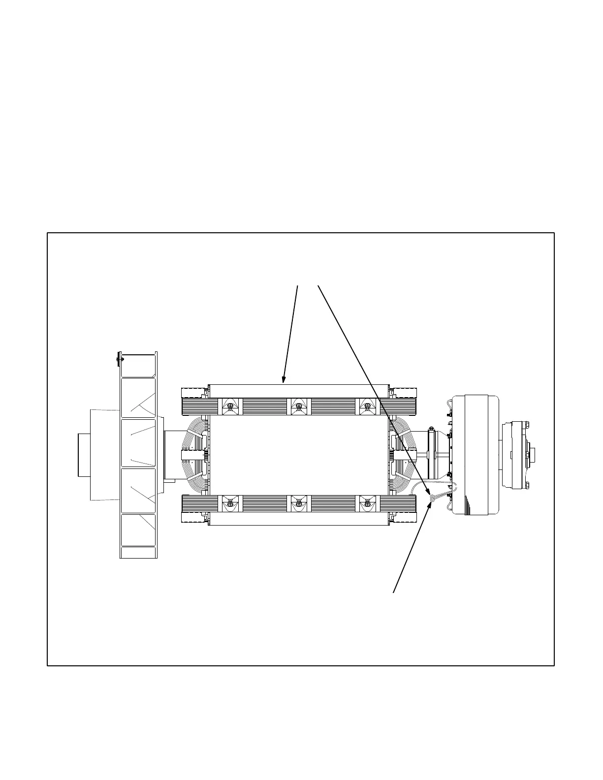
MAIN ROTOR (ALTERNATOR FIELD)
Testing Winding Resistance: Disconnect the two
leads of the main rotor from the terminals on the ro-
tating rectifier assembly. See Figure 6-5. Measure
electrical resistance between the two leads with a
Wheatstone bridge or digital ohmmeter. Replace
the rotor if the resistance is not as specified in Table
6-2. Connect the rotor leads and torque the termi-
nals to 23 in-lb (3.3 Nm) when reassembling.
Before performing the following insulation resist-
ance test, refer to the Insulation Resistance Test pro-
cedure at the beginning of this section.
Insulation Resistance and PI Test: Disconnect
the main rotor and voltage suppressor leads from
terminals F1+ and F2− on the rotating rectifier as-
semblies and isolate them from ground. Tag and
mark each lead with its terminal number (F1+ or
F2−).
Connect the megger between one of the rotor leads
and ground and conduct the test as instructed un-
der Insulation Resistance testing.
DISCONNECT THE MAIN ROTOR LEADS
FROM THE ROTATING RECTIFIER ASSEMBLY
AND MEASURE THE WINDING RESISTANCE
BETWEEN THEM
MEASURE WINDING INSULATION
RESISTANCE BETWEEN EITHER ROTOR
LEAD AND THE ROTOR LAMINATIONS
FIGURE 6-5. TESTING THE MAIN ROTOR