3-6
Copyright 2017 Cummins Inc.
ANALOG BOARD (A33)
The analog board (Figure 3-5) is the only circuit
board inside the control that has no LED’s. There
are two versions of the analog board that are used
for paralleling and non-paralleling systems.
This board interprets all analog input signals and
converts the analog signals to 0−5 VDC for the digi-
tal board.
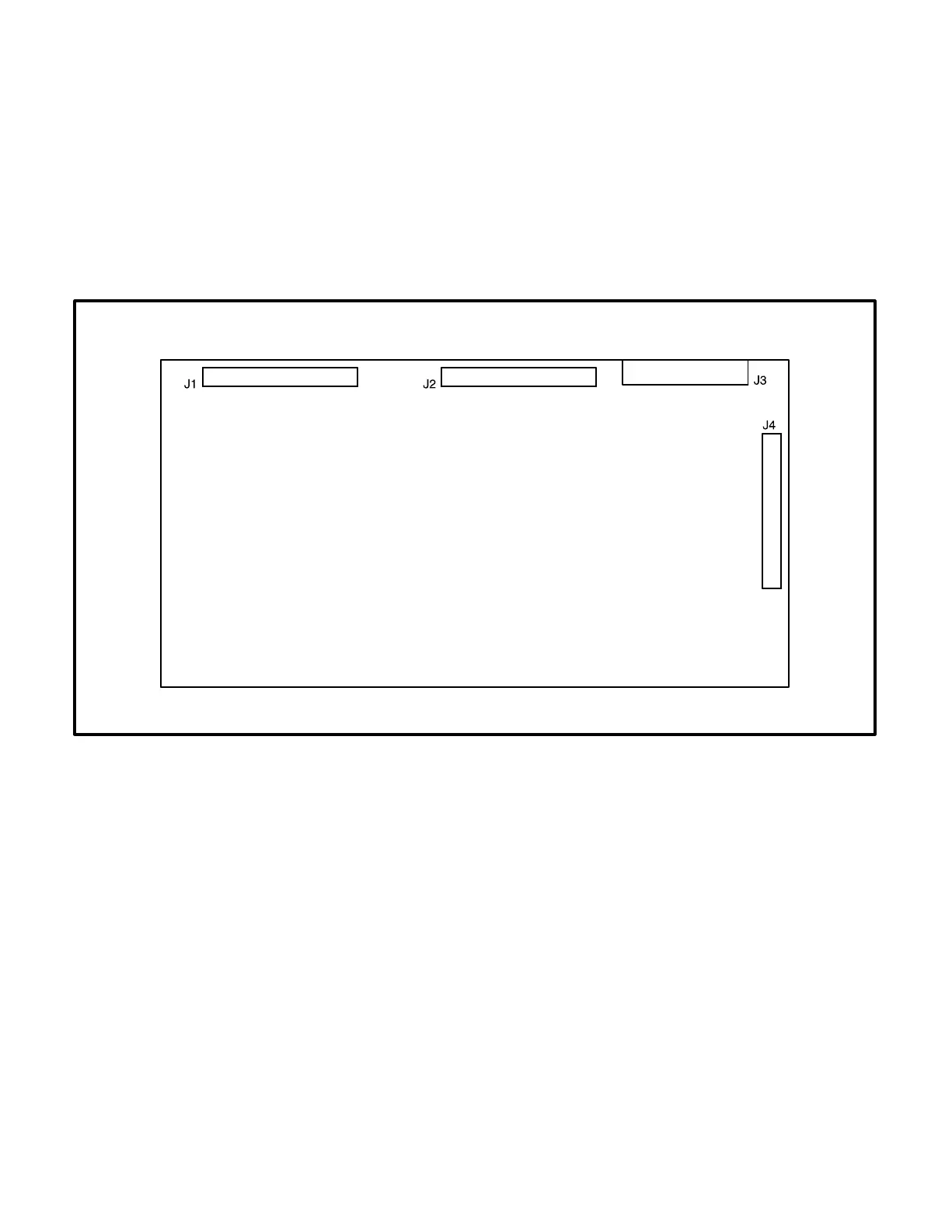
Connectors
The analog board has four connectors with ribbon
cables permanently soldered to them. They are:
J1 Connects to J2 on A31 Engine Interface
board
J2 Connects to J3 on A32 Digital board
J3 Spare analog inputs
J4 Connects to J1 on A34 Customer Interface
board
FIGURE 3-5. ANALOG BOARD