4-2
Copyright 2017 Cummins Inc.
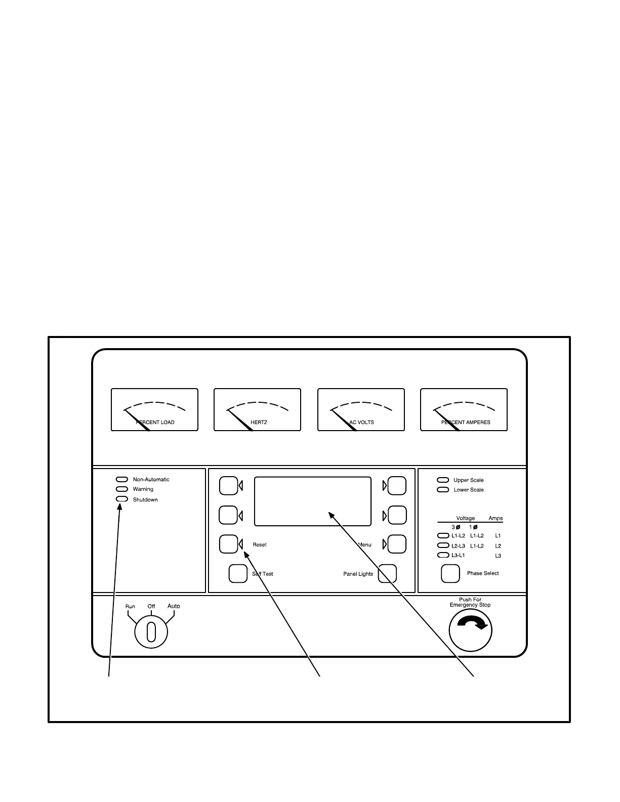
STATUS INDICATORS
Non-Automatic Status Indicator: This red lamp
flashes continuously when the Run/Off/Auto switch
is in the Off position.
Warning Status Indicator: This yellow lamp is lit
whenever the control detects a warning condition.
After the condition is corrected, warning indicators
can be reset by pressing the Reset switch. (It is not
necessary to stop the generator set.) In auto mode,
warning indicators can also be reset by cycling the
remote reset input after the condition is corrected.
Shutdown Status Indicator: This red lamp is lit
whenever the control detects a shutdown condition.
Shutdown faults are latched. After the condition is
corrected, shutdown indicators can be reset by
turning the Run/Off/Auto switch to the Off position,
and pressing the Reset switch. In the Auto position,
shutdown faults can be reset by removing the re-
mote start input and then cycling the remote reset
input.
Emergency Stop shutdown status (Code 102) can be
reset only at the PCC front panel.
Digital Display: This two-line, 16-character per line
alphanumeric display is used in the menu-driven
operating system and to show shutdown and warn-
ing messages. Refer to Tables 4-1 and 4-2.
RESETTING THE CONTROL
Press the momentary Reset Switch to reset warn-
ing and shutdown messages after the condition has
been corrected. To reset a shutdown message with
the Reset switch, the Run/Off/Auto switch must be
in the Off Position. (The control cannot go into
Standby (sleep) mode until all faults have been
reset.)
In Auto mode, warning indicators can also be reset
by cycling the remote reset input after the condition
is corrected. Shutdown faults can be reset by re-
moving the remote start input and then cycling the
remote reset input.
ALPHANUMERIC
FAULT MESSAGE
DISPLAY
RESET
SWITCH
WARNING AND
SHUTDOWN
STATUS INDICATORS
FIGURE 4-1. CONTROL PANEL