3-11
Copyright 2017 Cummins Inc.
VOLTAGE REGULATOR OUTPUT MODULE
(A37)
The voltage regulator output module (Figure 3-9) is
a power Amplifier. This board is used to amplify the
pulse-width modulated (PWM) signal from the PCC
to drive the exciter windings. Power from the PMG is
used by this board to amplify the PWM signal.
Connectors
The voltage regulator output module has two con-
nectors. They are:
J7 Connects to engine harness (control)
J7 wiring connections:
Gray Regulator Drive (+) Input
White Regulator Drive (-) Input
Blue B+ Input (RUN signal)
Purple Ground Input
Grn/Yel Start in
Black Start solenoid
J10 Connects to engine harness (power)
J10 wiring connections:
Green Phase A PMG power
Yellow Phase B PMG power
Orange Phase C PMG power
Red X (Field +) Output
Brown XX (Field −) Output
LEDs
The voltage regulator output module has 3 LED’s
that indicate the following conditions.
DS1 On when voltage regulator isolated supply is
operating (Green)
DS2 Output Duty Cycle − Brighter when load in-
creases − larger duty cycle (Amber). The duty
cycle range of the PWM signal is 0 - 60%. Be-
cause the normal duty cycle is less than 10%,
the output duty cycle LED, DS2 will normally
be very dimly lit.
DS3 Backup start disconnect − On when start dis-
connect is true (Green). The backup start dis-
connect is initiated at about 850 RPM, when
sensed PMG voltage is greater than 105 volts
RMS.
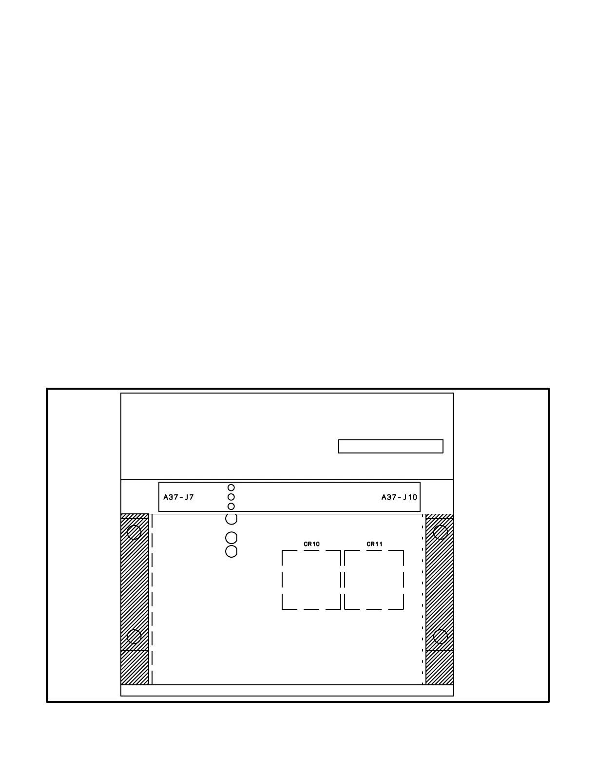
J10J7
DS1 - ISOLATED SUPPLY
DS2 - OUTPUT DUTY CYCLE
DS3 - BACKUP START DISCONNECT
FIGURE 3-9. VOLTAGE REGULATOR OUTPUT MODULE (A37)