3-10
Copyright 2017 Cummins Inc.
PT/CT BOARD (A36)
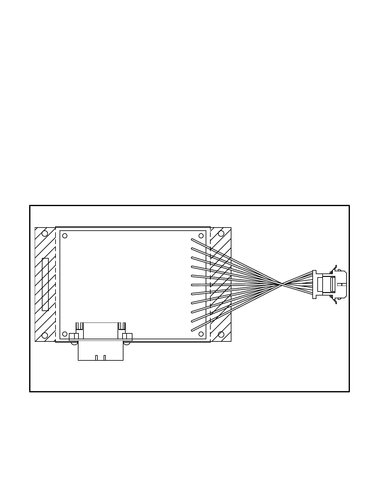
The PT/CT board (Figure 3-8) is mounted inside the
accessory box. This board converts alternator out-
put voltage to approximately 18 VAC levels for the
analog board. It also converts CT .55 Amp (at full
load) output to approximately 1.65 VAC (at full load)
input for the analog board.
There are three versions of this board. For proper
operation, the PT/CT board must be correctly
matched to the generator set.
In addition, there is a specific set of CTs for each
generator set. For proper operation, the CTs must
also be correctly matched to the generator set out-
put current.
Connectors
The PT/CT board has two connectors. They are:
J8 Connects to J3 on A34 Customer Interface
board
J9 Connects to AC harness (alternator output
voltage and CTs)
J9 wiring connections:
Yellow Gen. A In
Orange Gen. B In
Red Gen. C In
Brown Gen. Common In
White CT21 (+) In
Gray CT21 (common) In
Grn/Ylw CT22 (+) In
Black CT22 (common) In
Purple CT23 (+) In
Blue CT23 (common) In
J8
J9
FIGURE 3-8. PT/CT BOARD