3-1
Copyright 2017 Cummins Inc.
3. Circuit Boards and Modules
GENERAL
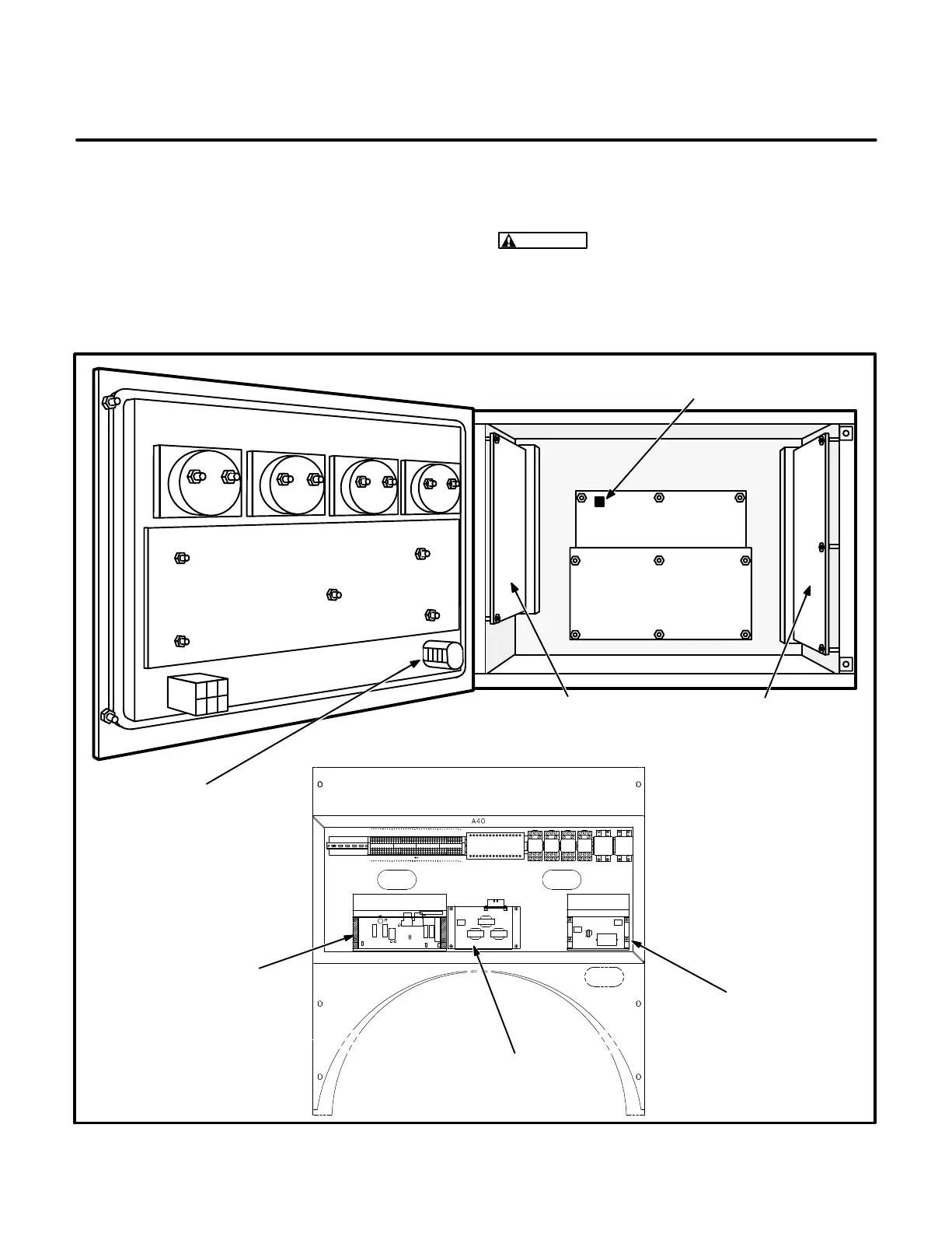
This section describes the function of the PCC cir-
cuit boards and modules that are contained in the
control panel (Figure 3-1) and the accessory box.
The block diagram in Figure 3-2, shows both inter-
nal and external components of the PCC system.
The system schematics are provided in Section 7 of
this manual.
CAUTION
Electrostatic discharge will damage
circuit boards. Always wear a grounding wrist
strap when touching or handling circuit boards
or socket-mounted ICs.
CUSTOMER INTERFACE
A34
ENGINE INTERFACE
A31
ANALOG BOARD
A33
DIGITAL BOARD
A32
DISPLAY BOARD
A35
RUN/OFF/AUTO
SWITCH S12
S5 POWER ON/
STANDBY SWITCH
GOVERNOR
OUTPUT MODULE
A38
PT/CT
BOARD A36
VOLTAGE
REGULATOR
OUTPUT MODULE
A37
FIGURE 3-1. CIRCUIT BOARD LOCATIONS