4-39
Copyright 2017 Cummins Inc.
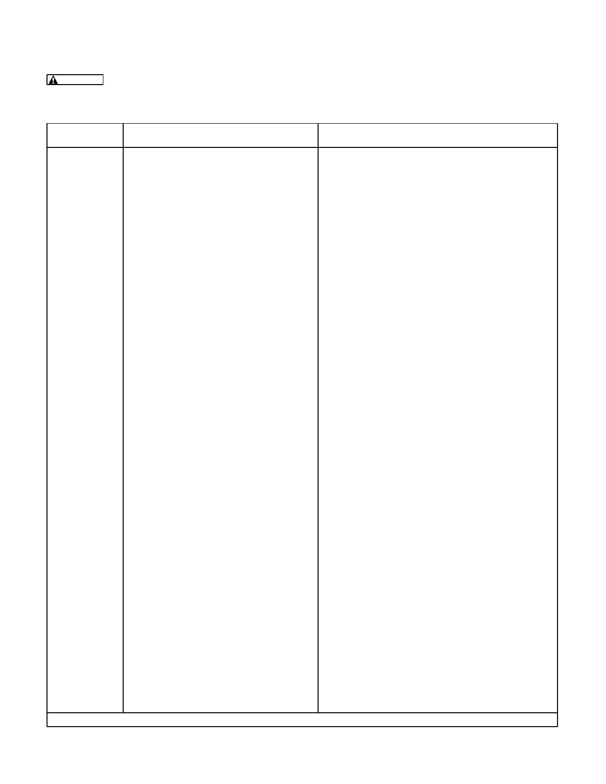
TABLE 4-27A. LOW AC VOLTAGE SHUTDOWN (303)
WARNING
Many troubleshooting procedures present hazards that can result in severe personal inju-
ry or death. Only qualified service personnel with knowledge of fuels, electricity, and machinery haz-
ards should perform service procedures. Review Important Safety Instructions page.
Indicator(s) Possible Cause Corrective Action
“LOW AC
VOLTAGE ”
shutdown
(303)
message.
1. PMG or field wiring could be faulty.
2. The rotating rectifier assembly (diodes
CR1 through CR6) is faulty.
3. Overload.
4. There may be a loose connector in the
control loop.
5a. The problem may be the analog board
(A33) or the digital board (A32).
5b. The problem may be the regulator
module (A37), the engine interface
board (A31), or the digital board (A32).
1. If output voltage is low and both A37/DS2 and
A31/DS10 are on, check and repair the PMG or
field wiring.
2. Check each diode according to Servicing the
Alternator in Section 6. Service as necessary.
3. Check the load and correct any overload.
4. Check connectors J8 and J9 on A36, J3 and J5
on A34, and J7 on A37.
*5. Isolate the generator set output from the load.
Reset the control, restart the generator set, and
measure AC output voltage with a multimeter.
a. If output voltage is high, refer to the trouble-
shooting section for High AC Voltage Shutdown
(301).
If output voltage is normal, the problem must be
in the voltage sensing circuitry (A32 or A33).
Isolate, using the analog input troubleshooting
procedure (Table 4-29a/b). Check the phase
that shows a low voltage on the PCC display.
*b. If output voltage is low, the control cannot drive
the output voltage high enough. The problem
could be A37, A31, or A32. Restart the genera-
tor set and monitor isolated B+ supply LED
A37/DS1,
output duty cycle LED A37/DS2, and
AVR duty cycle LED A31/DS10.
If A37/DS1 is not on, disconnect A3 J7/P7
and check for B+ at P7-1. (Control must be in
Run mode for B+ reading.)
If B+ is OK to A37, replace A37.
If A37/DS1 is on, check A31/DS10 (with the
generator set running).
If A31/DS10 is not on with generator set run-
ning, check for continuity: A31 J1-2 to J4-10
and A31 J1-1 to J4-11 (270 ohms). If no con-
tinuity, replace A31.
If A31is OK, replace A32.
If A31/DS10 is on with generator set running
and A37/DS2 is not on, check the harness.
If the harness is OK, replace A37.
*CAUTION: Wearing a wrist strap, set S12 to Off and A32 S5 to Standby before connecting/disconnecting harness plugs.
(Continued)