4 — PROGRAMMABLE PARAMETERS
Curtis AC F4-A Motor Controller – August 2020 Return to TOC
pg. 94
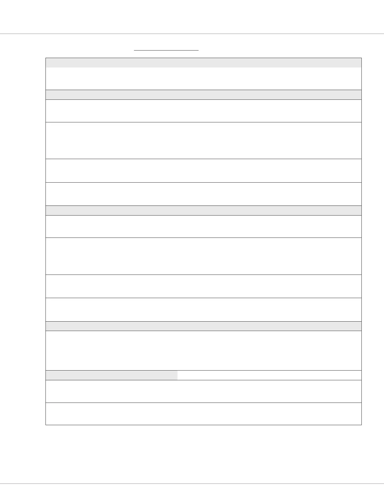
CONTROLLER SETUP — INPUTS MENU, cont’d
PARAMETER ALLOWABLE RANGE DEFAULT DESCRIPTION
High
Analog_Input_8_High
0x3308 0x00
0.0 – 30.0 V
0 – 3000
30.0 V The maximum input voltage before a fault is declared.
This voltage is the 100% point for the normalized inputs.
Analog 9 menu
Voltage
analog_input_volts_9
0x3B36 0x00
–327.68 – 327.67
–32768 – 32767
Read Only
V
Voltage at pin 24.
Percent
Analog_Input_Percent_9
0x3B40 0x00
0.0 – 100.0 %
0 – 1000
Read Only Voltage on a 0-100 percentage basis, pin 24.
The percentage of the voltage at pin 24 based upon the High and
Low settings. i.e., the % of:
((analog_input_volts_9) – (analog_input_9_low)) /
((analog_input_9_high – (analog_input_9_low))
Low
analog_input_9_low
0x3301 0x00
0.0 – 30.0 V
0 – 3000
0.0 V The minimum input voltage before a fault is declared.
This voltage represents the 0% point for the normalized inputs.
High
analog_input_9_high
0x3302 0x00
0.0 – 30.0 V
0 – 3000
30.0V The maximum input voltage before a fault is declared.
This voltage is the 100% point for the normalized inputs.
Analog 14 menu
Voltage
Analog_Input_Volts_14
0x3B38 0x00
–327.68 – 327.67
–32768 – 32767
Read Only
V
Voltage at pin 25 (as the +12V External Supply in Fig 6).
Percent
Analog_Input_Percent_14
0x3B42 0x00
0.0 – 100.0 %
0 – 1000
Read Only Voltage on a 0-100 percentage basis, pin 25.
The percentage of the voltage at pin 25 based upon the High and
Low settings, i.e., the percent of:
((analog_input_volts_14) – (analog_input_14_low)) /
((analog_input_14_high) – (analog_input_14_low))
Low
Analog_Input_14_Low
0x3303 0x00
0.0 – 30.0 V
0 – 3000
0.0 V The minimum input voltage before a fault is declared.
This voltage represents the 0 % point for the normalized inputs.
High
Analog_Input_14_High
0x3306 0x00
0.0 – 30.0 V
0 – 3000
30.0V The maximum input voltage before a fault is declared.
This voltage is the 100% point for the normalized inputs.
Analog 18 menu
Analog 18 Type
Analog_Input_18_Type
0x330F 0x00
Enumeration
0 – 3
Voltage Congure the Analog 18 input by throttle or load type.
0 – Voltage (Hall-effect or voltage throttle)
1 – 3-Wire Pot Wiper (3-wire resistive potentiometer throttle)
2 – 2-Wire Pot Wiper (2-wire resistive potentiometer throttle)
3 – Voltage with Supply (a non-throttle load alternative)
Parameters for Analog 18 Voltage selection Reference the Voltage Throttle section, Chapter 6
Analog 18 Type
Analog_Input_18_Type
0x330F 0x00
Voltage
(selection menu)
– Selecting the Voltage option opens the menu to its corresponding
monitor variables and the low/high parameters.
Voltage
Analog_Input_Volts_18
0x3B60 0x00
–327.68 – 327.67
–32768 – 32767
Read Only
V
The analog voltage at the input pin 17.
Quick Links:
Voltage rottle p.136
3-Wire rottle p.135
2-Wire rottle p.135
Fig. 6 p.10
 Loading...


