5 — SYSTEM MONITOR MENU
Curtis AC F4-A Motor Controller – August 2020 Return to TOC
pg. 122
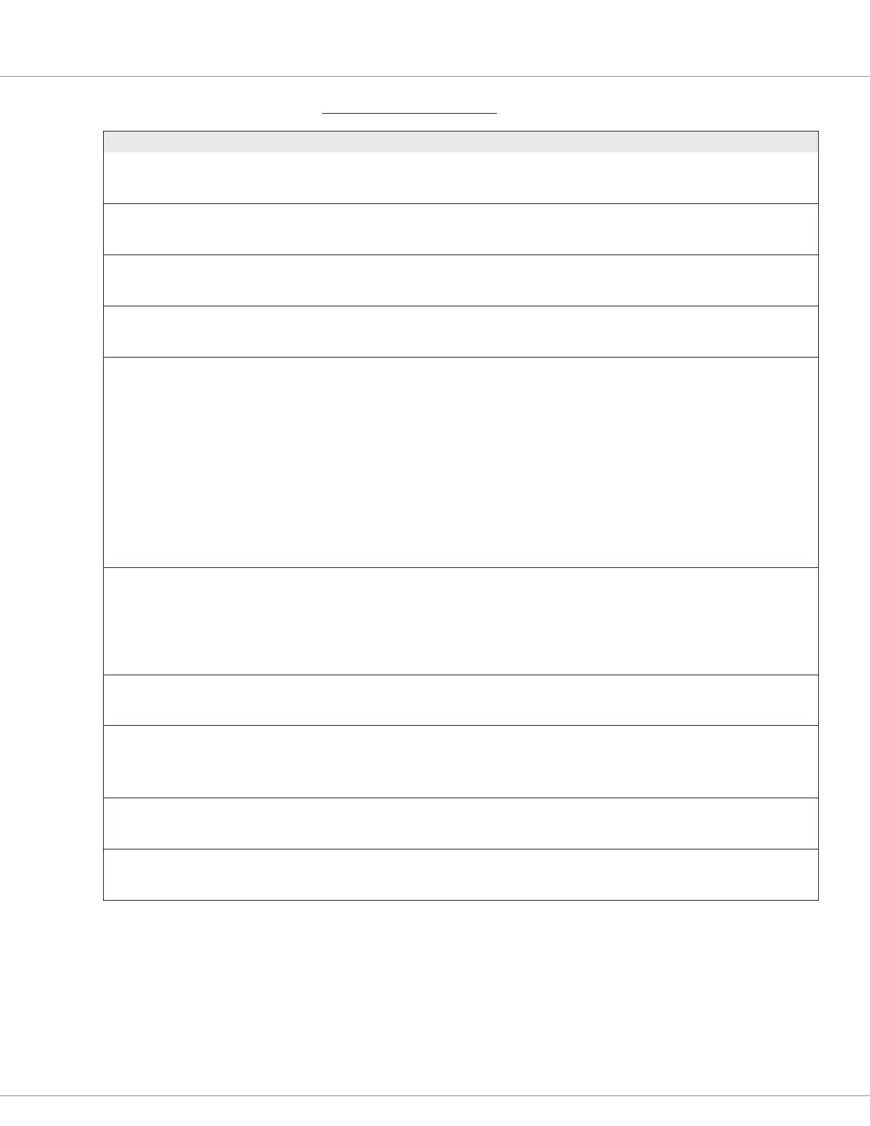
SYSTEM MONITOR MENU: CONTROLLER
VARIABLE DISPLAY RANGE DESCRIPTION
Current (RMS)
Current_RMS
0x3082 0x00
0.0 – 1000.0 A
0 – 10000
The RMS current of the controller, taking all three phases into account.
Modulation Depth
Modulation_Depth
0x30B0 0x00
0.0 – 100.0 %
0 – 1182
The usage percentage of the available B+ voltage.
Frequency
Frequency
0x3090 0x00
–500 – 500 Hz
–30000 – 30000
The Controller’s electrical frequency.
Controller Temperature
Controller_Temperature
0x3000 0x00
–100.0 – 300.0 °C
–1000 – 3000
The Controller’s internal temperature (on the power base).
Main Contactor State
Main_State
0x34C9 0x00
0 – 10
0 – 10
Main contactor state:
0 = open
1 = precharge
2 = weld check
3 = closing delay
4 = missing check
5 = closed (when Main Enable = On)
6 = delay
7 = arc check
8 = open delay
9 = fault
10 = closed (when Main Enable = Off)
EM Brake State
EMBrakeState
0x347A 0x00
0 – 4
0 – 4
EM brake state:
0 = engaged
1 = releasing
2 = released
3 = engaging
4 = engaged and vehicle stopped
EMR State
EMR_State
0x3490 0x00
0 – 1
0 – 1
0 = Off
1 = On
NMT State
CAN_NMT_State
0x32A4 0x00
0 – 127
0 – 127
Controller CAN NMT state:
0 = initialization
4 = stopped
127 = pre-operational
Regen
Regen
0x30BA 0x00
0 – 1
0 – 1
1 = Regenerative Braking (mode)
0 = Drive (mode)
Master Timer
master_timer
0x4E14 0x00
0.0 – 429496729.5 s
0 – 4294967295
The manager timer is a timer of the total controller hours (keyswitch “on”
hours). This manager timer is part of the operating system (OS) and is not
resettable.
 Loading...


