10
Curtis 1298 Manual, OS 11
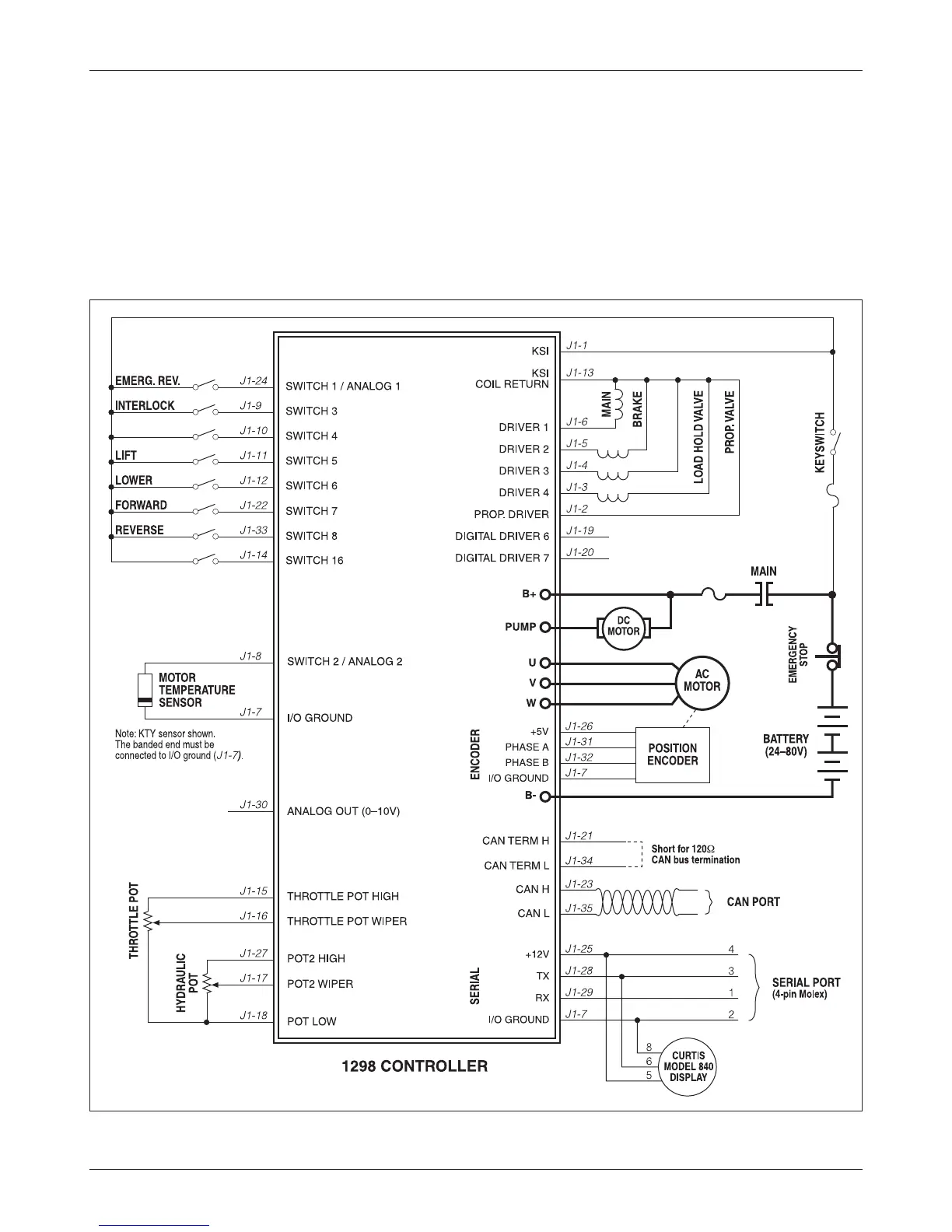
Fig. 3 Basic wiring diagram, Curtis 1298 motor controller.
2 — INSTALLATION & WIRING: Standard Wiring Diagram
CONTROLLER WIRING: BASIC CONFIGURATION
A basic wiring diagram is shown in Figure 3. The throttles are shown in the
diagram as 3-wire potentiometers; other types of throttle inputs are easily ac-
commodated, and are discussed in the following throttle wiring section.
The main contactor coil must be wired directly to the controller as shown
in Figure 3 to meet EEC safety requirements. The controller can be programmed
to check for welded or missing contactor faults and uses the main contactor