16
Curtis 1298 Manual, OS 11
2 — INSTALLATION & WIRING: I/O Signal Specifications
INPUT/OUTPUT SIGNAL SPECIFICATIONS
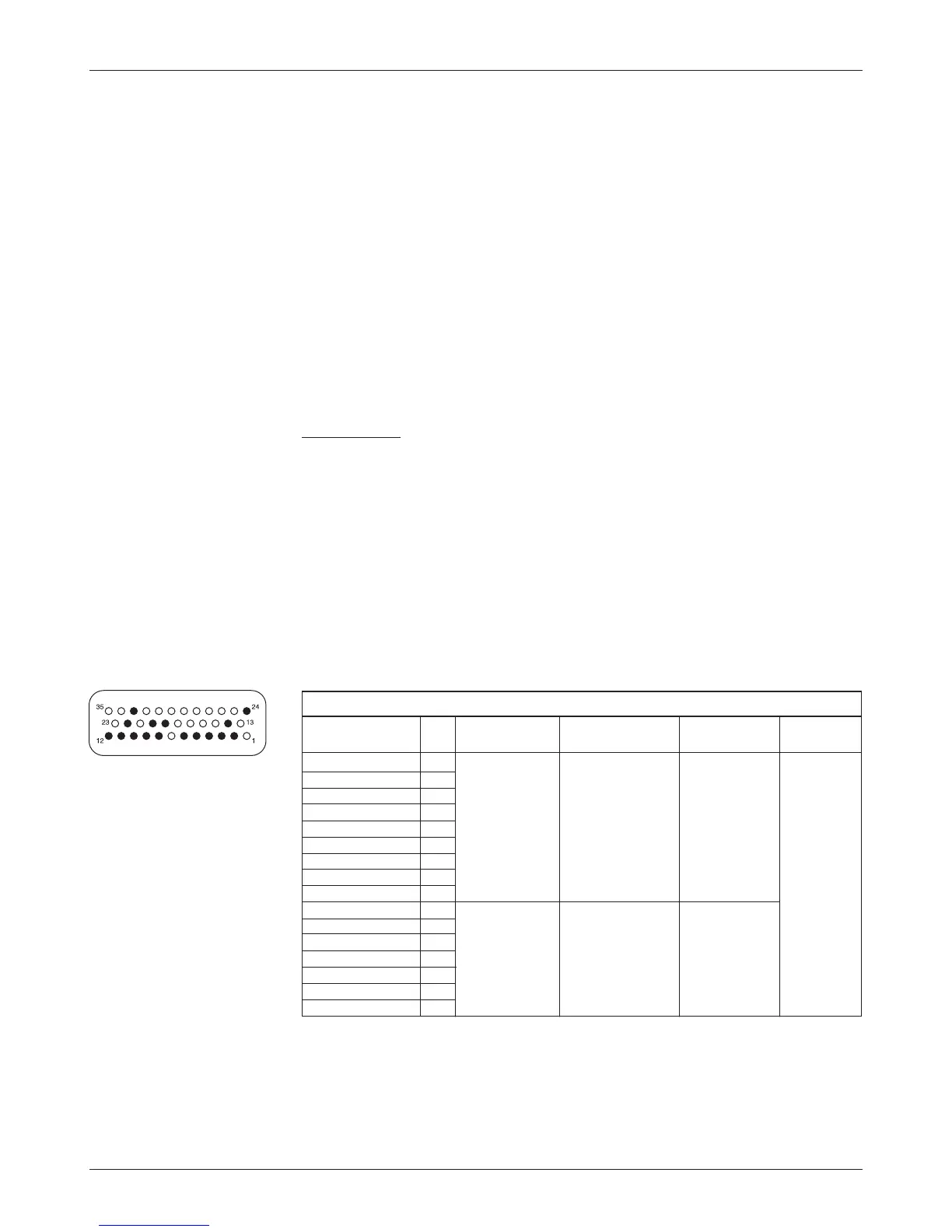
The input/output signals wired to the 35-pin connector can be grouped by
type as follows; their electrical characteristics are discussed below.
— digital inputs
— high power outputs
— analog inputs
— analog output
— power supply outputs
— KSI and coil return inputs
— throttle and brake inputs
— communications port inputs/outputs
— encoder inputs.
Digital inputs
These control lines can be used as digital (on/off) inputs. Normal “on” connection
is direct to B+; “off” is direct to B-. Input will pull low (off) if no connection
is made. All digital inputs are protected against shorts to B+ or B-.
Nine of these lines (Switches 1–8, 16) are designed to pull current to keep
switch contacts clean and prevent leakage paths from causing false signals.
The remaining lines are digital inputs associated with driver outputs; note
that they have much higher input impedances. The two digital output lines can
also be read as inputs, and are therefore included in this group.
The lines at pins 24 and 8 can also be used as analog inputs, and are
included in that group as well.
DIGITAL INPUT SPECIFICATIONS
LOGIC
INPUT VOLTAGE ESD
SIGNAL NAME PIN THRESHOLDS
IMPEDANCE RANGE
*
TOLERANCE
Switch 1 24 Rising edge= 24V models: -10 V to ± 8 kV (air
Switch 2 8 4.4 V max
about 7.1 kΩ (MaxV + 10 V) discharge)
Switch 3 9 Falling edge= 36-48V models:
Switch 4 10 1.5 V min about 11.0 k
Ω
Switch 5 11 48-80V models:
Switch 6 12 about 26.0 k
Ω
Switch 7 22
Switch 8 33
Switch 16 14
Digital Out 6 19 Rising edge= Below 10 V= - 0.5 V to
Digital Out 7 20 4.4 V max 300 k
Ω (MaxV + 10 V)
Driver 1 6 Falling edge= Above 10 V=
Driver 2 5 1.5 V min 150 k
Ω
Driver 3 4
Driver 4 3
Prop Driver 2
*
“MaxV” in this and the following tables is the controller’s maximum voltage: 30 V for 24V models,
and 45 V for 24–36V models.