Curtis 1298 Manual, OS 11
93
7 — VCL
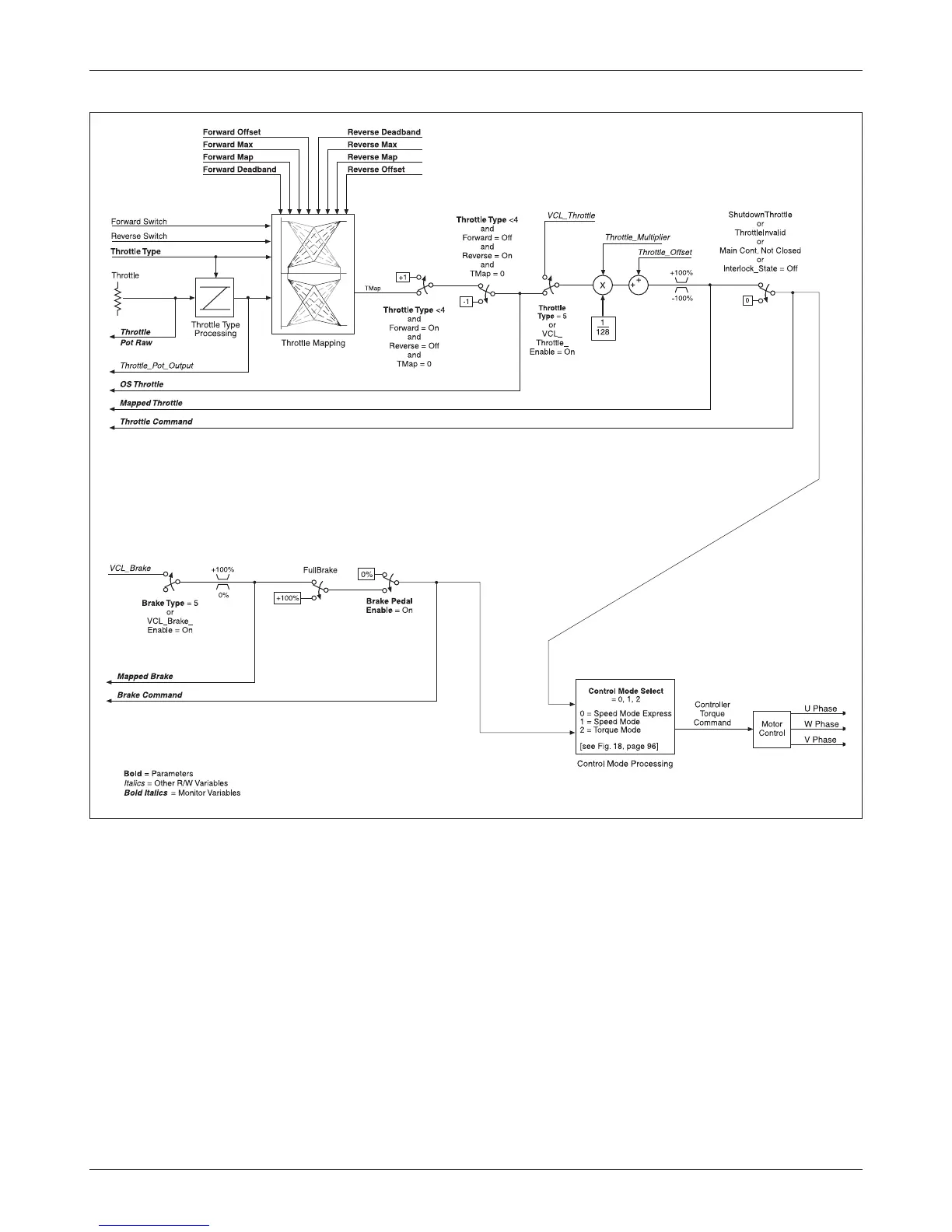
Fig. 17 Motor command diagram, AC traction motor.
After the “Throttle Type = 5” switch, the throttle signal is modified by the
multiplying and summing nodes. These nodes can be adjusted by VCL through
the variables Throttle_Multiplier and Throttle_Offset. This is the basic input
point for creating functions like MultiMode, dual drive algorithms, and height
vs. speed control. Note that the throttle multiplier has a built-in “divide by 128.”
This allows the VCL to either multiply (Throttle_Multiplier > 128) or divide
(Throttle_Multiplier < 128) the nominal throttle value. Typically the default
multiplier is set to 128, thus having no net effect. Both Throttle_Multiplier
and Throttle_Offset can be positive or negative.
The output of the multiplying and summing nodes is a VCL variable
called Mapped_Throttle, which is displayed in the 1311 Monitor
» Input menu.
Checking the value of Mapped_Throttle using the 1311 is a good way to see if