88
Curtis 1298 Manual, OS 11
VCL RUNTIME RATES
VCL is an interpreted language. Each line of VCL code is converted (compiled)
into a set of codes and then flash loaded into the controller. The controller
interprets these codes one line at a time while the system is powered up. Here
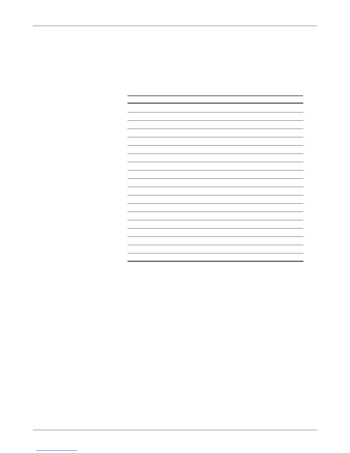
are the processing rates of the various functions:
FUNCTION FUNCTION FULL NAME INSTANCES SERVICE RATE
ABS Absolute Value 2 4 ms
ADC Analog to Digital Converter Input 2 1 ms
CAN CAN Communications 15 4 ms
CPY Copy 8 4 ms
DLY Delay 32 1 ms
FLT Filter 4 1 ms
LIM Limit 4 4 ms
MAP Map 4 4 ms
MTD Multiply then Divide 4 4 ms
NVM Non-Volatile Memory 38 2 ms
PID Proportional Integral Derivative 2 4 ms
POT Potentiometer Input 2 8 ms
PWM Pulse Width Modulated Output 6 4 ms
RMP Ramp 4 1 ms
SCL Scaling 4 4 ms
SEL Selector, 2-position switch 8 4 ms
SEL_4P Selector, 4-position switch 8 32 ms
SW Switch Input 1
* 4 ms
TMR Timers (hourmeters) 3 1 ms
* There is only one Switch variable; it has 16 associated bit-variables.
I/O CONTROL WITH VCL
Digital Inputs
The 1298 controller has a total of 16 digital inputs. Eight are switch inputs
(Sw_1 through Sw_8, plus Sw_16). These switch inputs are shown on the
standard wiring diagram (Figure 3, page 10). The remaining seven digital
inputs are less obvious: one on each driver and digital output (Sw_9 through
Sw_15). These can be used as digital inputs or to sense the state of the output
or its wiring (e.g., open coil check).
To address a digital input in a VCL program, use the desired input label
(Sw_1 through Sw_16). You must use On or Off in the code when determining
a switch state; using true/false or 1/0 will give erroneous results.
7 — VCL