44
Curtis 1298 Manual, OS 11
3 — PROGRAMMABLE PARAMETERS: Main Contactor Parameters
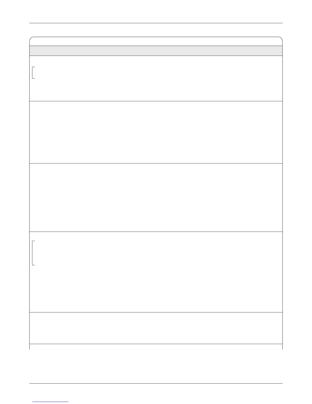
MAIN CONTACTOR MENU
ALLOWABLE
PARAMETER RANGE DESCRIPTION
Main Enable On/Off When programmed On, the controller’s native software controls the main
Main_Enable On/Off contactor when the interlock is enabled or when Pump_Throttle >0.
OptionBits1 [Bit 0] When programmed Off, the contactor is controlled by VCL. Note: With
Main Enable programmed Off, the controller will not be able to open the
main contactor in serious fault conditions and the system will therefore not
meet EEC safety requirements.
Pull In Voltage 0–100 % The main contactor pull-in voltage parameter allows a high initial voltage
Main_Pull_In_Voltage 0–32767 when the main contactor driver first turns on, to ensure contactor closure.
After 1 second, this peak voltage drops to the contactor holding voltage
.
To protect the driver hardware from overcurrent, the software puts a
limitation on driver output PWM. A PWM output of 1–59% is not allowed
and the software will “round up” the PWM to 60%. Setting this parameter
to a value <60% will therefore result in an output PWM of at least 60%.
Note: The Battery Voltage Compensated parameter (below) controls
whether the pull-in and holding voltages are battery voltage compensated.
Holding Voltage 0–100 % The main contactor holding voltage parameter allows a reduced average
Main_Holding_Voltage 0–32767 voltage to be applied to the contactor coil once it has closed. This param
-
eter must be set high enough to hold the contactor closed under all shock
and vibration conditions the vehicle will be subjected to
.
To protect the driver hardware from overcurrent, the software puts a
limitation on driver output PWM. A PWM output of 1–59% is not allowed
and the software will “round up” the PWM to 60%. Setting this parameter
to a value <60% will therefore result in an output PWM of at least 60%.
Note: The Battery Voltage Compensated parameter (below) controls
whether the pull-in and holding voltages are battery voltage compensated.
Battery Voltage Compensated On/Off This parameter determines whether the main pull-in and holding voltages
Main_Driver_Battery_Voltage_ On/Off are battery voltage compensated. When set On, the pull-in and holding
Compensated voltages are set relative to the set Nominal Voltage (see Battery menu,
Main_Driver_Battery_Voltage_ page 55). In other words, the output voltage is adjusted to compensate for
Compensated_Bit0 [Bit 0] swings in battery voltage, so the percentage is relative to the set Nominal
Voltage—not to the actual voltage.
For example, suppose Nominal Voltage is set to 48V and Holding
Voltage is set to 75% (36V) to the output driver. Now suppose the bus volt
-
age dips to 40V. If Battery Voltage Compensated = On, the output will still
be 36V (Nominal Voltage × Holding Voltage) to the coil. If Battery Voltage
Compensated = Off, the output will be 30V (Actual Voltage × Holding Volt-
age) to the coil.
Interlock Type 0–2 Three interlock options are available:
Interlock_Type 0–2 0 = interlock turns on with switch 3.
1 = interlock controlled by VCL functions.
2 = interlock turns on with KSI.