6
Curtis 1298 Manual, OS 11
2 — INSTALLATION & WIRING: High C.000urrent Connections
cables should not run across the center section of the controller. Low current
signal wires should not be run next to the motor cables. When necessary they
should cross the motor cables at a right angle to minimize noise coupling.
Motor wiring (U, V, W)
The three phase wires should be close to the same length and bundled together
as they run between the controller and the motor. The cable lengths should be
kept as short as possible. Use high quality copper lugs and observe the recom-
mended torque ratings. For best noise immunity the motor cables should not
run across the center section of the controller. In applications that seek the
lowest possible emissions, a shield can be placed around the bundled motor
cables and connected to the B- terminal at the controller. Typical installations
will readily pass the emissions standards without a shield. Low current signal
wires should not be run next to the motor cables. When necessary they should
cross the motor cables at a right angle to minimize noise coupling.
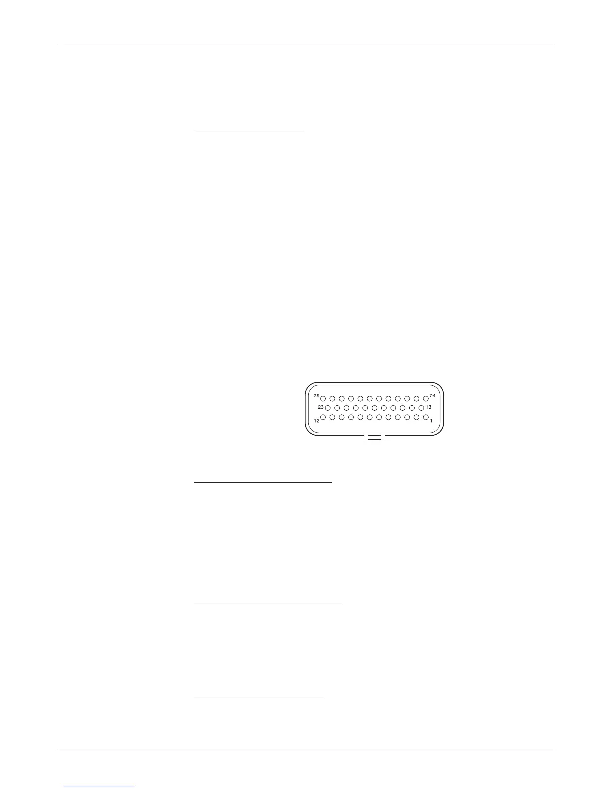
LOW CURRENT CONNECTIONS
All low power connections are made through a single 35-pin AMPSEAL con
-
nector. The mating plug housing is AMP p/n 776164-1 and the contact pins
are AMP p/n 770520-3. The connector will accept 20 to 16 AWG wire with
a 1.7 to 2.7mm diameter thin-wall insulation.
The 35 individual pins are characterized in Table 2.
Low current wiring recommendations
Motor encoder (Pins 31, 32)
All four encoder wires should be bundled together as they run between the
motor and controller logic connector. These can often be run with the rest of
the low current wiring harness. The encoder cables should not be run near
the motor cables. In applications where this is necessary, shielded cable should
be used with the ground shield connected to the I/O ground (pin 7) at only
the controller side. In extreme applications, common mode filters (e.g. ferrite
beads) could be used.
CAN bus (Pins 21, 23, 34, 35)
It is recommended that the CAN wires be run as a twisted pair. However,
many successful applications at 125 kBaud are run without twisting, simply
using two lines bundled in with the rest of the low current wiring. CAN wiring
should be kept away from the high current cables and cross it at right angles
when necessary.
All other low current wiring
The remaining low current wiring should be run according to standard practices.
Running low current wiring next to high current wiring should always be avoided.
J1