Curtis 1298 Manual, OS 11
53
3 — PROGRAMMABLE PARAMETERS: Hydraulic Parameters
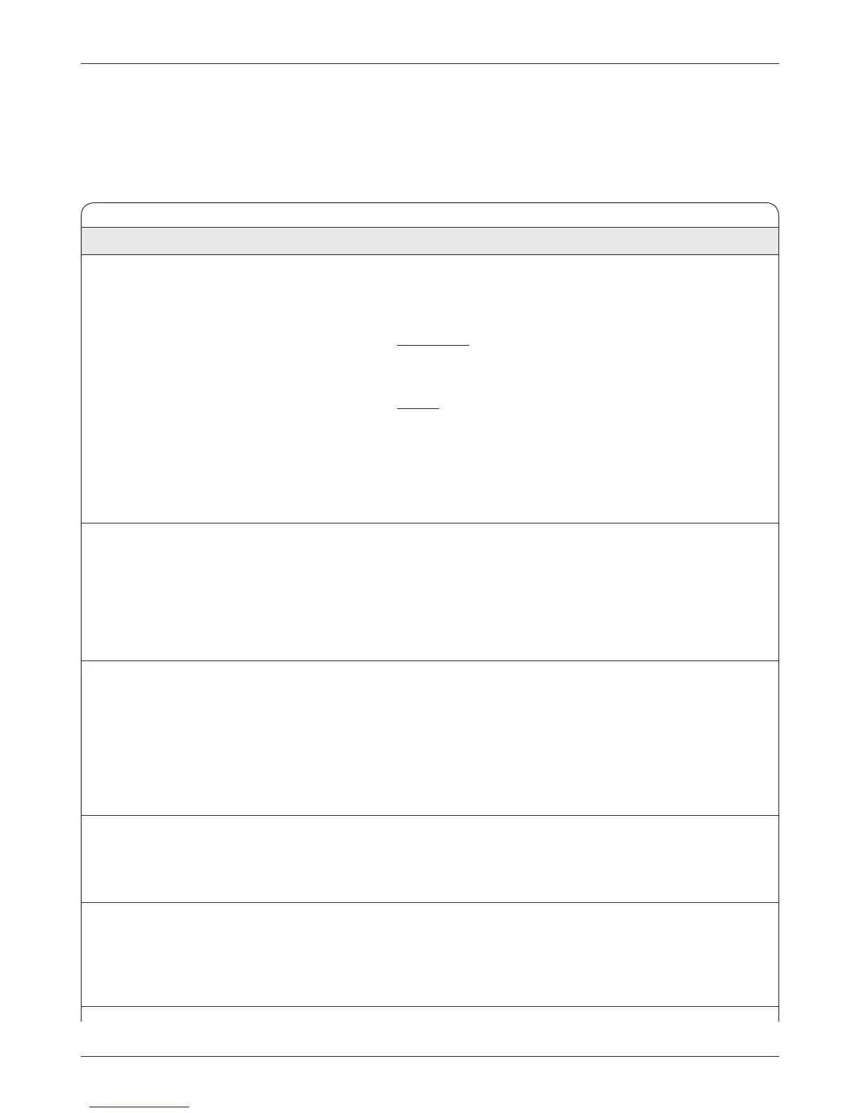
HYDRAULIC THROTTLE MENU
ALLOWABLE
PARAMETER RANGE DESCRIPTION
Hyd Throttle Type 1–5 The 1298 controller accepts a variety of throttle inputs. The hydraulic
Hyd_Throttle_Type
1–5 throttle type parameter can be programmed as follows:
1 2-wire rheostat, 5k
Ω–0 input
2
single-ended 3-wire 1kΩ–10kΩ potentiometer,
or 0–5V voltage source
3 2-wire rheostat, 0–5k
Ω input
4 wigwag 3-wire 1k
Ω–10kΩ potentiometer,
or 0–5V voltage source
5 VCL input (
VCL_Hyd_Throttle)
Note: Any time this parameter is changed a Parameter Change Fault (fault
code 49) is set and must be cleared by cycling power; this protects the
controller and the operator
.
Lift Deadband
0–5.00 V Defines the wiper voltage at the hydraulic throttle deadband threshold.
Lift_Deadband 0–32767 Increasing the hydraulic throttle deadband setting will increase the neu
-
tral range.
This parameter is especially useful with throttle assemblies that do
not reliably return to a well-defined neutral point, because it allows the
deadband to be defined wide enough to ensure that the controller goes
into neutral when the throttle mechanism is released.
Lift Map
10–100% Modifies the pump’s response to the hydraulic throttle input. Setting
Lift_Map 3276–32767 the lift map at 50% provides linear output response to hydraulic throttle
position. Values below 50% reduce controller output at low hydraulic
throttle settings, thus providing enhanced low-speed control of the pump.
Values above 50% give the pump a faster, more responsive feel at low
throttle positions.
The map value is the percentage of controller output at half throttle
((deadband + max) / 2).
Lift Max
0–5.00 V Defines the wiper voltage required to produce 100% pump output.
Lift_Max 0–32767 Decreasing the lift max setting reduces the wiper voltage and therefore
the full stroke necessary to produce full pump output. This parameter al
-
lows reduced-range throttle assemblies to be accommodated.
Lift Offset
0–100% Defines the initial pump output generated when the hydraulic throttle is
Lift_Offset 0–32767 first rotated out of the neutral deadband. For most pump systems, a set
-
ting of zero is appropriate. For some pump systems, however, increasing
the offset may improve controllability by reducing the amount of throttle
required to start the pump load moving.
For variable speed control, a throttle is required. Without a throttle, when the
Lift switch is closed the pump accelerates to the set maximum pump speed in
the set Pump Accel time; when the Lower switch is closed, the lowering valve
current ramps from 0% to 100% in the set Lower Accel time.