14
Curtis 1298 Manual, OS 11
the return path. This is the throttle shown in the basic wiring diagram (Figure 3)
for the drive throttle and for the hydraulic throttle.
The ET-XXX electronic throttle is typically used only as a drive throttle.
The ET-XXX contains no built-in fault detection, and the controller will detect
only open wiper faults. It is the responsibility of the OEM to provide any ad
-
ditional throttle fault detection necessary.
Throttle Type 3
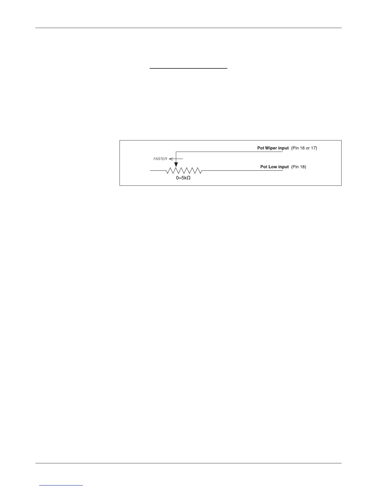
For these 2-wire resistive potentiometers, shown in Figure 6, full throttle request
corresponds to 5 k
Ω measured between the pot wiper pin and the Pot Low pin.
2 — INSTALLATION & WIRING: Throttle Wiring
Broken wire protection is provided by the controller sensing the current flow
from the wiper input (pin 16 or 17) through the potentiometer and into Pot
Low (pin 18). If the Pot Low input current falls below 0.65 mA, a throttle
fault is generated and the throttle request is zeroed. Note: Pot Low (pin 18)
must not be tied to ground (B-).
Throttle Type 4
Type 4 throttles operate in wigwag style. No signals to the controller’s forward
and reverse inputs (or Lift and Lower inputs) are required; the direction is
determined by the wiper input value. Only 0–5V voltage sources and 3-wire
potentiometers can be used as Type 4 throttles. The controller interface for
Type 4 throttles is the same as for Type 2 throttles; see Figure 5. The neutral
point will be with the wiper at 2.5 V, measured between pot wiper input
(pin 16) and I/O ground return (pin 7). The controller will provide increas
-
ing forward (Lift) speed as the wiper input value is increased, and increasing
reverse (Lower) speed as the wiper input value is decreased.
When a 3-wire pot is used, the controller provides full fault protection.
When a voltage throttle is used, the controller will detect open breaks in the
wiper input but cannot provide full throttle fault protection.
Throttle Type 5
Throttle Type 5 provides a different way of sending the throttle command to the
controller. This throttle type uses VCL to define the throttle signal that will be
“input” into the throttle signal chain; see Figures 16 and 18. This throttle type
can be used for either the drive throttle or the hydraulic throttle by using the
VCL variables VCL_Throttle and VCL_Hyd_Throttle. How the VCL program
is written will determine where the throttle signal originates from, making this
a very flexible throttle input method. VCL can be written to use the throttle
Fig. 6 Wiring for Type 3
throttles.