Curtis 1298 Manual, OS 11
17
Digital outputs
Seven control lines can be used as high power digital output drivers. One of
these, the proportional driver, can be operated in a current control mode for
driving a proportional valve or similar load. Each output can be independently
turned on continuously (low level) or pulse width modulated to set the average
output voltage. These outputs are intended to drive inductive loads such as
contactors and electromagnetic brakes but could also be used to drive resistive
loads if peak current ratings are not exceeded. All these outputs are protected
against shorts to B+ or B-.
These lines can also be used as digital inputs, and are included in that
group as well.
2 — INSTALLATION & WIRING: I/O Signal Specifications
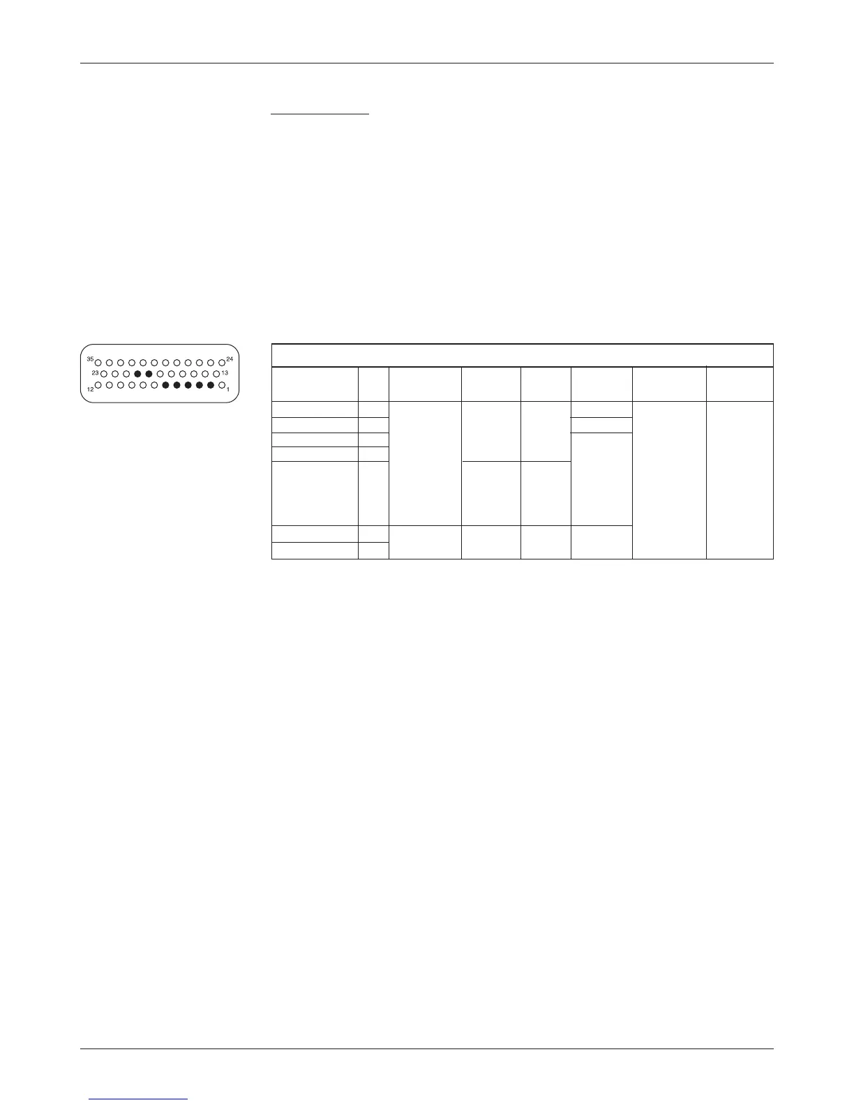
DIGITAL OUTPUT SPECIFICATIONS
PV FREQ- OUTPUT PROTECTED ESD
SIGNAL NAME PIN PWM
CURRENT UENCY CURRENT
*
VOLTAGE TOLERANCE
Driver 1 6 0 to 100% n/a 200 Hz 2 A max - 0.5 V to ± 8 kV (air
Driver 2 5 duty cycle 3 A max keyswitch discharge)
Driver 3 4 2 A max voltage
Driver 4 3
Prop Driver 2 0 to 2 A 18 kHz
in 607
nominal
steps
Digital Out 6 19 on/off n/a n/a 2 A max
Digital Out 7 20
* The combined current supplied
by all seven output drivers should not exceed 10 A.
To protect the driver hardware from overcurrent, the software puts a
limitation on driver output PWM. When in voltage control (typically using
parameters to control the main contactor or EM brake, or using the VCL func
-
tion Put_PWM) a PWM output of 1–59% is not allowed and the software will
“round up” the PWM to 60%. For example, the statement Put_PWM(PWM3,
16383) would result in an output PWM of 60% (even though the argument
16383 would normally be expected to result in an output PWM of 50%).
This limitation on the output PWM also holds true for the main contactor
driver PWM output that is set when the parameter Main Contactor Enable
= On. With Main Contactor Enable = On, the Pull In Voltage and Holding
Voltage parameters set the PWM output percent, but values of 1–59% will be
rounded up to 60%.
When the parameter PD Enable = On, the PD driver is current controlled
and thus is not affected by the overcurrent limitations which means a full range
of 0–100% PWM is allowed on this PD driver output.
☞